Categories:
-
3d 96 articles
-
animations 16 articles
-
architecture 47 articles
-
blender 98 articles
-
bédé 19 articles
-
techdrawing 24 articles
-
freecad 183 articles
-
gaming 1 articles
-
idsampa 8 articles
-
inthepress 8 articles
-
linux 57 articles
-
music 1 articles
-
nativeifc 24 articles
-
opensource 260 articles
-
orange 4 articles
-
photo 16 articles
-
projects 35 articles
-
receitas 176 articles
-
saopaulo 18 articles
-
sketches 162 articles
-
talks 25 articles
-
techdrawing 24 articles
-
textes 7 articles
-
trilhas 3 articles
-
urbanoids 1 articles
-
video 47 articles
-
webdesign 7 articles
-
works 151 articles
Archives:
-
2007 22 articles
-
2008 32 articles
-
2009 66 articles
-
2010 74 articles
-
2011 74 articles
-
2012 47 articles
-
2013 31 articles
-
2014 38 articles
-
2015 28 articles
-
2016 36 articles
-
2017 41 articles
-
2018 46 articles
-
2019 59 articles
-
2020 18 articles
-
2021 20 articles
-
2022 7 articles
-
2023 25 articles
-
2024 7 articles
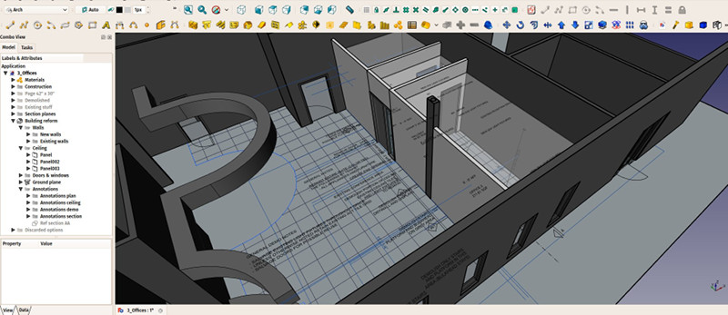
So, let's continue to post more often about FreeCAD. I'm beginning to organize a bit better, gathering screenshots and ideas during the week, so I'll try to keep this going. This week has seen many improvements, specially because we've been doing intense FreeCAD work with OpeningDesign. Like everytime you make intense use of FreeCAD or any other app, you spot a lot of smaller bugs and repetitive annoyances. But a look a the commits log will inform you that many of those have already been fixed on the way.
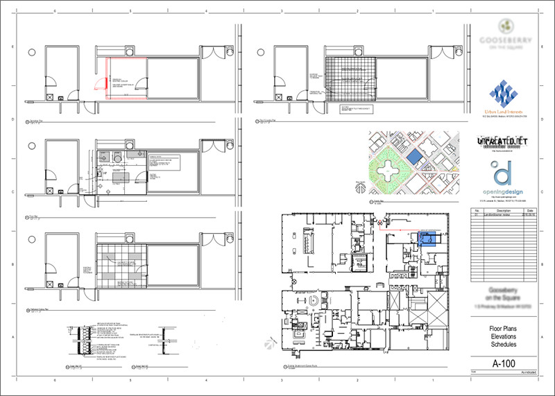
The above image shows one of these jobs, more about it below
Generally speaking, working with FreeCAD is becoming very stable. Drafting and modelling is very straightforward already, and the workflow even begins to become fast. The biggest bottleneck I encountered during this week is using the Drawing workbench to build 2D sheets of the model. This is mostly due to the limitations of Qt's SVG engine, which doesn't support the full SVG specification, and many features like clipping, multiline texts or hatches are not supported by the Drawing viewer. When exporting your final Drawing sheet to SVG, however, and opening it in a better SVG-supporting application such as Inkscape, Firefox or Chrome, the result is very good. But it is annoying to have to work in the Drawing module without seeing the actual result (that's actually the main reason why there is a "preview in browser" button in Drawing).
But, bearing with these difficulties, it is already totally possible to produce this kind of result:
This is about to change, however, with the new TechDraw workbench that is currently already available in development versions of FreeCAD (refer to previous posts to obtain one). TechDraw is not based directly on SVG anymore, but on the more generic graphics engine of Qt. The final SVG sheet that it produces is built from it, at the moment you export, but what you see while you are working is not the SVG data itself anymore. This might seem more complex (it is, actually), but opens up a huge array of possibilities. Most of the limitations above don't exist anymore in TechDraw.
Of the two main tools that we use in architectural and BIM work to build 2D sheets, which are the Draft view and the SectionPlane view (which is also built with the Drawing Draft tool), so far only the Draft view has been implemented in TechDraw, once the Section View tool is implemented too we can think of abandoning the Drawing for good.
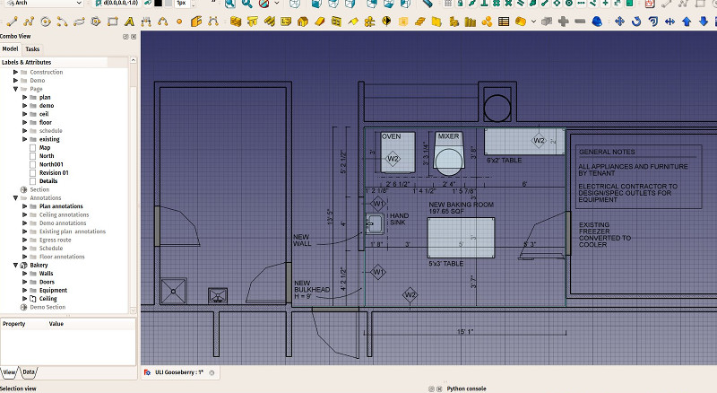
I'll describe a bit more of the workflow used in the jobs illustrated in this post. Almost everything was done directly in FreeCAD. The only pieces done outside were the cleaning of the existing floor plan, that we got in DWG form, in DraftSight, and the preparing of the Drawing template, and a couple of SVG objects to be placed directly on it, in Inkscape. All the rest is pure FreeCAD.
The basic workflow was this:
- Clean of unnecessary stuff in the DWG file, reduce number of layers, export it to DXF (in DraftSight)
- Import the DXF file in FreeCAD
- Draw a couple of lines and wires on top of the walls and columns of the existing floor plan (You can draw walls and structural elements directly, but I like to draw the baselines myself, to make sure they are where I want them, and I find the Draft tools much more convenient to draw stuff).
- Turn all your lines and wires to walls or structures (this whole thing is actually almost as fast as drawing them directly)
- Adjust thickness, height, alignment, etc... of walls and structures
- Put everything in groups. For me a huge power of FreeCAD over other BIM applications is the free grouping possibilities. By creating groups, and groups inside groups, you are basically organizing your data the way you want. No limitations, no rigid building/foor structure to follow. All the separation of, for example, the existing walls, the new walls and the walls to be demolished is simply done with groups.
- Add doors and windows. In most cases I didn't use the "in-wall" capability of windows, I made the openings first by subtracting a volume, then made the doors outside of any wall, and simply cloned them and moved them to their final places. This is bit slower, but makes your geometry much more failsafe, since windows are a delicate matter and still have bugs here and there.
- Add annotations, linework, texts, dimensions, in 2D, directly in the model (in the future, we hope to do most of this directly in TechDraw, but at the moment this "old-school" workflow is solid and works well. Again, separate annotations in groups, depending on the subject.
- Add one or more Section Planes to define plans and sections you'll need. If you grouped your objects well, you will only have one or two groups to add to the section plane as "seen objects". It is best to leave all the 2D geometry and annotations out, and have section planes only see 3D objects (being Arch or not).
- Prepare a Drawing template in Inkscape
- Create a new sheet in FreeCAD's Drawing workbench, give it our template, and start adding our stuff there, by using the Draft View tool, either with section planes selected (for cut or viewed 3D geometry), or groups containing linework, texts and dimensions (for 2D and annotations). This will allow you to create only a few Drawing views, so it keeps manageable.
- The clip tool of the Drawing workbench is annoying to use (it draws a big black rectangle on the sheet, which is not exported fortunately), so it's best to think about your layout beforehand, and model only what will appear on the sheet.
- Use the Drawing symbol and annotation tools to add stuff (logos, titles, etc) directly on the sheet.
- Export to SVG, open in Inkscape, there you have a chance to do more last-minute fixes if needed, and save as PDF. It is possible to export a PDF directly from FreeCAD, but opening it in another app is good to make sure everything is OK.
- Finally, in order to export to IFC, gather the arch objects inside a Building, export, and you are done. It is always a good idea to verify the exported IFC file in another IFC viewer application to make sure everything is there an dat the right place. A quick fix for buggy objects is to force them to export to Brep (there is a command for that in Arch -> Utilities).
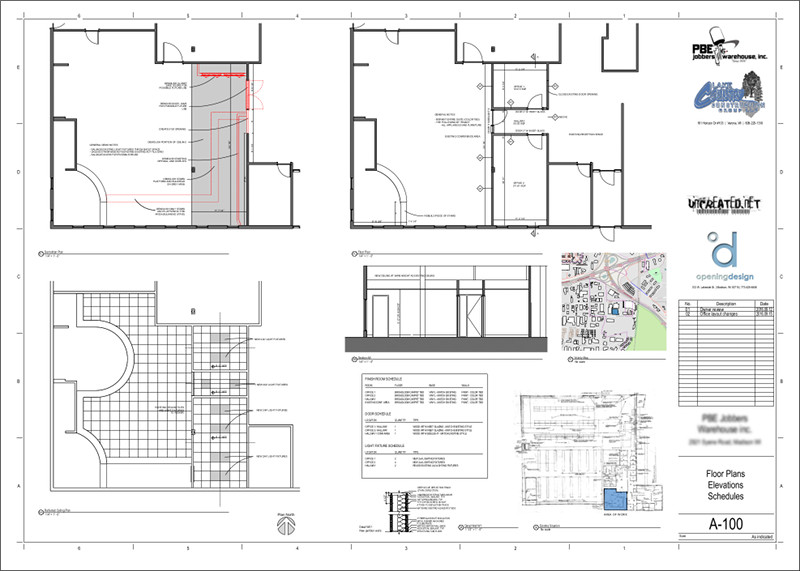
Interesting detail, the small city map in the images above, is taken directly from OpenStreetMap. There you have a "share" button that exports to SVG. You can then open that in Inkscape, rework it a bit if you like (change some colors and linetypes, etc), save it and place it directly on your Drawing sheet.
Of course this workflow above is somewhat distant than what you are used to with commercial BIM applications. But things are improving, and also this is not necessarily something negative. It also gives you a lot more freedom, and the mix of 2D and 3D that FreeCAD offers, that you had in the old times of AutoCAD or in apps like Rhino is something I find much valuable.
Don't forget that almost all the work of OpeningDesign is open, so all the files from the examples above are available online.
Finally, a word about two features I added this week, one is a new display mode for walls, which shows them in wireframe, but with the bottom face hatched, which makes it very nice to work in plan view
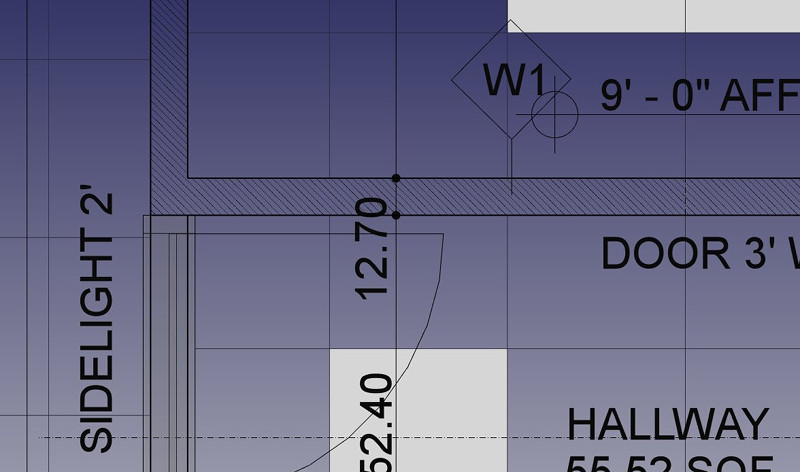
Right now it's still in testing, to see how useful it is and how well it behaves, but if it works well it should be extended to support different patterns (taken from the material, for example), and to extend this to structural objects too.
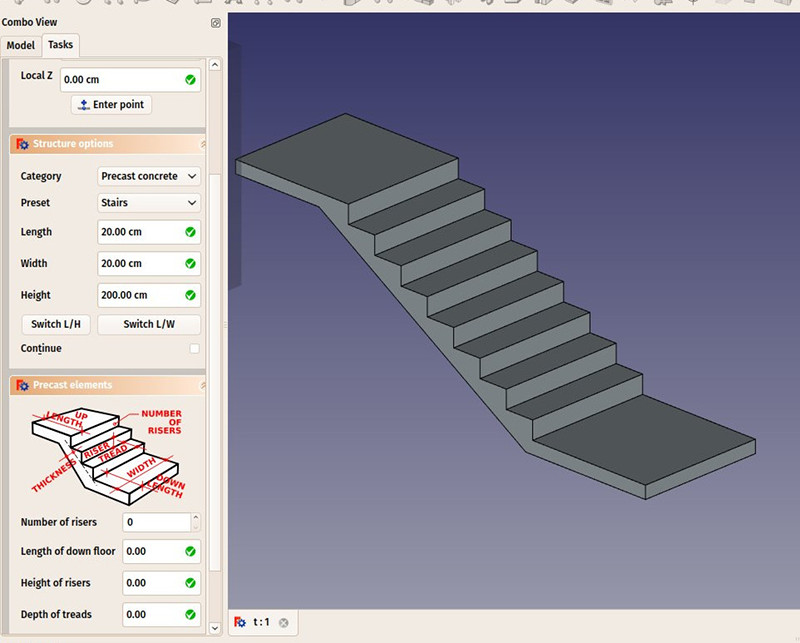
And finally, another feature is a new addition to the structural precast concrete presets, a stairs element: