Categories:
-
3d 96 articles
-
animations 16 articles
-
architecture 47 articles
-
blender 98 articles
-
bédé 19 articles
-
techdrawing 24 articles
-
freecad 183 articles
-
gaming 1 articles
-
idsampa 8 articles
-
inthepress 8 articles
-
linux 57 articles
-
music 1 articles
-
nativeifc 24 articles
-
opensource 260 articles
-
orange 4 articles
-
photo 16 articles
-
projects 35 articles
-
receitas 176 articles
-
saopaulo 18 articles
-
sketches 162 articles
-
talks 25 articles
-
techdrawing 24 articles
-
textes 7 articles
-
trilhas 3 articles
-
urbanoids 1 articles
-
video 47 articles
-
webdesign 7 articles
-
works 151 articles
Archives:
-
2007 22 articles
-
2008 32 articles
-
2009 66 articles
-
2010 74 articles
-
2011 74 articles
-
2012 47 articles
-
2013 31 articles
-
2014 38 articles
-
2015 28 articles
-
2016 36 articles
-
2017 41 articles
-
2018 46 articles
-
2019 59 articles
-
2020 18 articles
-
2021 20 articles
-
2022 7 articles
-
2023 25 articles
-
2024 7 articles
Here goes a little report from the FreeCAD front, showing a couple of things I've been working on in the last weeks.
Site
As a follow-up of this post, several new features have been added to the Arch Site object. The most important is that the Site is now a Part object, which means it has a shape. Before, it was only a group, it had no "physical" existence in the 3D world. It now behaves like other Arch objects, that is, it has a base property (which is here called "Terrain"), that contains a base terrain object, that, at the moment, must an open Part object. Later on it will be extended to also accept meshes.
Then you have two additional properties, "Additions" and "Subtractions", same as other Arch objects. These are set by double-clicking the Site object in the tree view. With these, you can add solid objects as subtractions and additions.
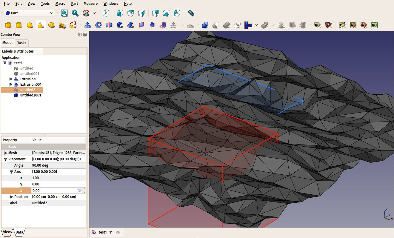
When adding these objects, the result you get is this:
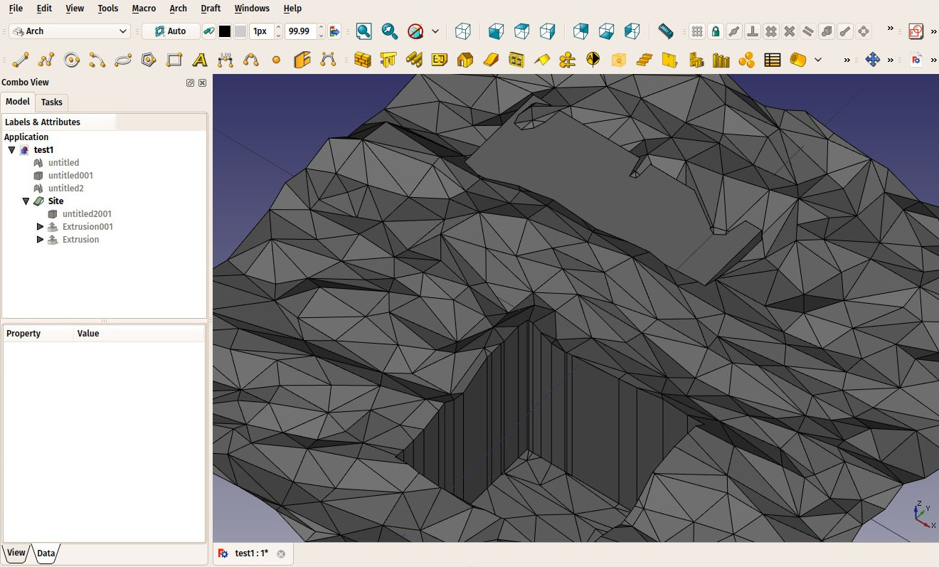
The difference with other Arch objects is that the site is always an open surface. It is not a solid. Other BIM apps usually require you to model a piece of solid to be the terrain, but I find that weird and arbitrary, most (all?) ways to obtain terrain data (GIS data, on-site measurements, etc) will give you only surface data. Why would the BIM app need a solid? Besides, in the long run, no doubt FreeCAD will gain tools for heavy civil engineering like roads and tunnels. These people certainly won't be satisfied with a simple block of uniform terrain. We'll need to be able to represent different geological layers. So sooner or later the solid representation would need to be changed.
It seems a safer bet to me to start slowly, and consider, for now, terrains as surfaces. Note that it is totally possible to interact with solids. In the images above, the red and blue shapes that get added/subtracted are solids. The result is a surface, but the Site object keeps track of the volumes of earth being excavated and filled in two separate properties (Addition Volume and Subtraction Volume). Additional properties will give you the terrain real area, the area of the projection on the XY (horizontal) plane, and the length of the perimeter.
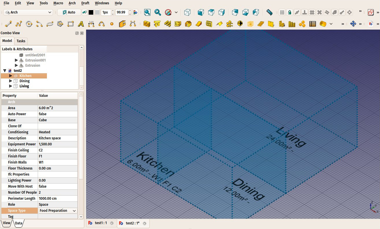
Spaces
I also did some more work on spaces. Basically, they received a couple of new properties such as vertical area, perimeter and a series of properties related to space use (number of people, energy consumption, etc) that will be needed for GBXML export. Note also that Equipment objects can now also have energy consumption defined, and you can have the consumption of spaces automatically calculated by summing the consumption of equipment inside it.
I also worked further on the GBXML exporter itself, but met a temporary showstopper. To test GBXML output, we need an application that can import GBXML and, preferably, do something with it. As far as I know, the only one avaialble that is open-source and runs on Linux is OpenStudio, which by the way seems a really nice thing. It is a bit hard to find the source code of OpenStudio, but it is on github. Problem: OpenStudio uses libraries about 2 years old (boost mainly) and doesn't run on modern Linux systems (their officially supported platform is an Ubuntu from 2012...) So I'm now busy trying to make OpenStudio work on my machine, which requires a ton of small fixes and is not a very easy task for a C++ ignorant. We could of course ask for help to the OpenStudio people, but the project has 691 open issues, I don't think we have a lot of chances to be heard.
If you read this and have some good knowledge of boost, I'd be very grateful for a little help!
About GBXML export from FreeCAD, it seems to me that the whole idea (looking at sketchup videos) of working with GBXML is to work with spaces. Spaces are the building blocks of a GBXML file. They have a series of properties, and each of their surfaces also has different properties such as material, orientation and what there is behind (exterior, ground or another space).
At the moment, spaces in FreeCAD are just containers for equipments, and carry information such as area. They can also be defined by boundary elements such as walls. But to make them work for GBXML, we'll need more, for example the ability to define a material for each surface, and also know if another space is behind a specific surface.
This would basically require spaces to touch each other, and not stop at walls like they do now. This might actually be easier for space calculations too. My idea at the moment is simply to make spaces behave differently when a wall or slab is used as boundary. Instead of stopping at the wall face, it would go up to the wall "midplane" (which will now need to be calculated). This way, any space would know 1) which material each surface is made of, by querying the material of the wall, and 2) which space is behind, by querying the wall for other attached spaces. All this should stay optinal of course, so you can still use spaces to calculate the "inner" area of a room.
Structural nodes
As discussed several times with Bernd, the official civil engineer of FreeCAD and one of the masterminds behind the FEM workbench, it is important to be able to extract an analytic model from structural elements in FreeCAD. Since quite some time, Arch structure elements have a "Nodes" property, which contains a list of 3D points. These form a linear sequence, that represents a structural line for the element. These nodes are calculated automatically, but can now also be edited manually, the same way as you can edit Draft objects. You can also easily make the nodes of several elements coincide, so it is now very easy to obtain analytic models like this:
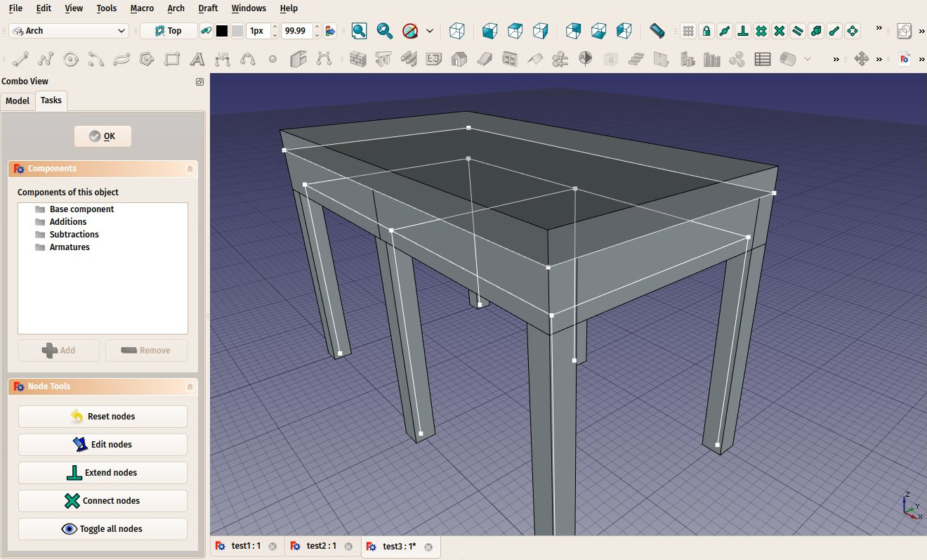
Note that the slab, on top of the beam, can have its nodes form a plane instead of a line. This will later on be added to walls too.
We are not sure how/where to export these models yet, I'll try to start with IFC, which supports such analytic representations. Later on, we'll see...
Panels
Panels also received a little upgrade that I needed for a project: The ability to represent corrugated panels like these:
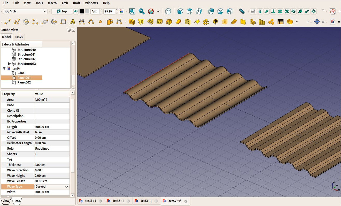
For this, a couple of new properties have been added to panels, where you can specify the type, direction, height and length of the waves. The rest continues to behave like before, so you just need to draw a 2D object, then press the Panel button to turn this 2D object into a panel.
Windows
Arch Windows could already have 3 kinds of components: frames, glass panels and solid panels. There is now a fourth: louvres. So now windows can also be used not only to make doors and windows, but also different kinds of shading devices.
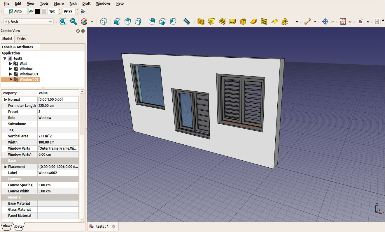
To add louvred panels to a window, all that is needed is to edit the window by double-clicking it in the tree view, selecting a component, and changing its type to louvre. Two new window properties, Louvre Width and Louvre Spacing, will control the size and spacing of the louvre elements.