|
URBAN DESIGN WITH BLENDER by Yorik- April 2006 |
In this article I'll try to describe a bit of two large-scale urban development projects that were made mostly with Blender, and the different techniques used to achieve the goal. I tried to write something that would be interesting for both Blender users who don't do architecture and for architects or urban planners who don´t use Blender. This article is more meant to be an illustration, food for your creativity, than a complete accurate tutorial. Feel free to copy any material found here (but don't copy the projects, make your own!). These two projects were made at and by Cabeza Sastre, São Paulo, Brazil.
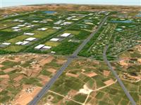
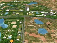
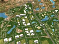
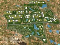
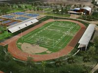
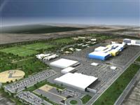
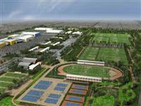
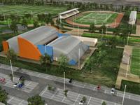
Here is the kind of results we got: (Click images to enlarge)
Project 1 : Almoloya de Juarez (México) – see full animation (GoogleVideo)
Project 2 : Ciudad de México (México) – see full animation (GoogleVideo)
1. GENERAL ISSUES
The two projects have very big scales (first one is 29 million m², second one is “only” 1,2 million m²...) so we absolutely needed to find techniques to avoid modelling as much as we could, and keep very simple objects. In case of project 2, we also wanted to do some close-ups because we have those “special spots” (olympic tracks, buildings...), so a couple of places are more detailed. These images show you more or less what complexity the scenes have:
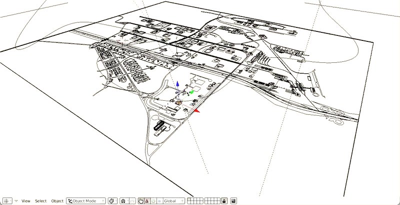
Above we have Almoloya, the first one, and below México.
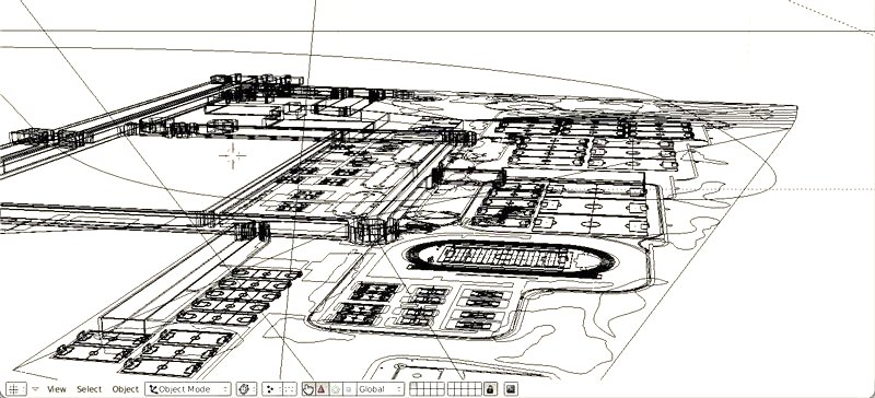
The
same with trees on:
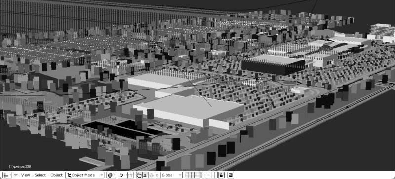
As you
can see, there are very few objects. In the first case, almost
everything was modelled directly in Blender, as I'll explain below.
In the second case, we had a pretty more detailed CAD drawing, so
most of the objects were imported from AutoCAD, and we modelled only
the buildings in Blender. In both cases, you always want to try to
avoid modelling and use mapping also as much as you can. In first
project, you see that only streets and buildings are modelled. All
the rest is made only with mapping.
An important point is that Blender doesn't like much scenes bigger that 1000 units... so if your projects has a dimension bigger than 1000 units (meters, kilometers, whatever), it's better to start with scaling down everything by 10 or 100, and just imagine you're working with units 10 times bigger. In these examples, we worked in meters but in Blender, every blender unit was 10 meters worth.
2. BACKGROUND
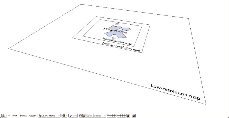
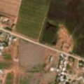
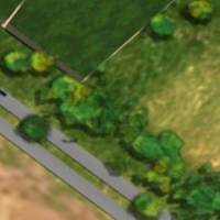
The background used in both cases is a mixture of maps taken from GoogleEarth. Since the program only lets you save very small images (unless you buy some commercial version), you need to join all the small images you saved into a big one, what we did with the Gimp. In our endless efforts to work less, we made several images with different resolution, since you don't need so much detail further away from the project center. Each image is then used as a map on a different plane, with a little vertical distance between each plane to avoid openGL artifacts.
|
|
|---|
|
|
|
|
The important point here is scale well the images from start. GoggleEarth has a measuring tool I found very accurate (I measured an olympic swimming pool I knew measured 25m, it gave me 25,15m...). Once you have a distance between 2 points on your image, you can know what are its total dimensions. When you know your image represents an area of let's say 300m x 400m, you just have to make a 300x400 plane (or 30x40) in Blender, and apply your image as mapping and you have your world at exact scale to work on. At this stage, it's a good idea to do some test renderings to check if the resolution is sufficient (we used the maximum resolution GoogleErath can give, which is high enough in most cases).
3. MODELLING
Here we used 2 different methods. The first one was modelling everything in Blender, and the other one importing almost everything from AutoCAD (which is what we use at office, but the procedure is almost the same with any CAD program).
First method: All in Blender
|
|
|
|
|
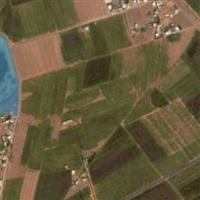
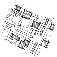
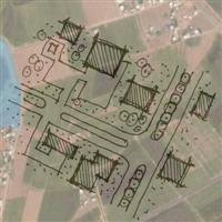
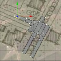
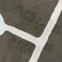
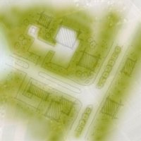
We started from the GoogleEarth map (1), layered on it in the Gimp the dirty hand-drawn sketches (2) we had for a project (if you don't have any, you can just skip this and go directly to step 4 below, and draw directly on the map), and we used that as a view background in Blender (3), in a top view. With your plane already scaled, it's easy to fit the background image in it.
Then you can just draw plane shapes on it, like you would in any CAD program (4). You start with a plane, select an edge or a single vertex, and CTRL-left-click to extrude your shape on top of your sketch. This goes very fast and requires very little vertex-by-vertex editing after. We made one shape for roads, one or two for special green areas, and one for buildings. Then again, you must leave a little space between each shape otherwise Blender gets a bit confused about which is above which.
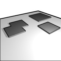
The buildings are modelled just the same way: Simple plane shapes that got a little extrusion:
Second method: Import shapes from CAD program
Here there is no difficulty, just draw your shapes in your favorite CAD program, always using closed polylines, and convert them into regions in AutoCAD, in solid shapes or meshes if your program doesn't have regions. You'll probably have to test a bit to find what type of object arrives in Blender as plane filled forms, but surely there is one. The best way to pass data from a CAD drawing to Blender is usually the 3DS format, since almost all CAD programs can export to it, and Blenders imports it very nicely. The aim is to import “plates” (i mean plane shapes) in Blender, since it's usually faster to draw 2d shapes in a CAD program, and faster to extrude the whole pack in Blender. Again, once you have your shapes in Blender, raise each one a little bit above the other.
4. MAPPING
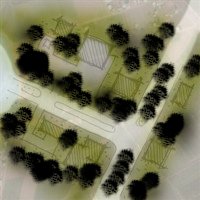
Here is the best part: You take back your GoogleEarth+Sketch image, open it in the Gimp, and add new layers, each one for a different “object” you want in Blender (for ex. different vegetation types, trees, pools, lakes, roadsides, sand zones, etc...). This is most useful when you do everything in Blender, since you don´t have any object yet, only the roads and your background plane.
On each layer, you can paint only with black if you're going to use it as a mask for a texture, which is better for large areas, or directly with color when you're adding details.
|
|
|
|
|
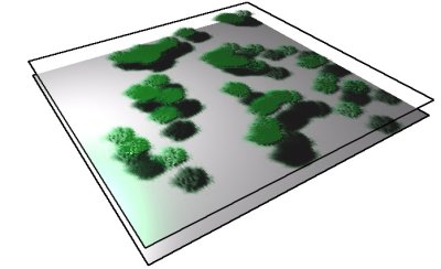
Once all of this is done, it´s just a matter of saving each layer as a separate image (png format is best since it keeps alpha values) and apply them as a texture on several copies of your background plane, all separated by a small space. You can mix several textures in one material if they are all ground materials, or create planes that are a bit higher, for example for trees, so trees will give a little shadow on the ground:
|
|
|
5. VEGETATION
In big architecture or urban projects, you always find yourself with the problem of vegetation. Above a single building with a few trees around (which looks quite poor), you always need to find “cheap” ways to stuff your project with low-rendering-cost-vegetation...
Here again, we used two different methods, according to the project type and scale.
Horizontal plane method:
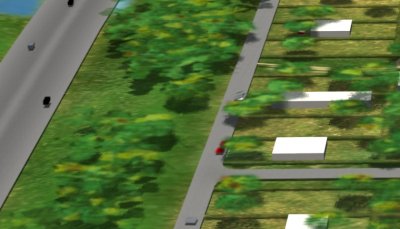
In the Almoloya case, the size is so huge that it wouldn't be realistic do object-by-object vegetation. We choosed to lay one big trees layer in top of everything since when you fly at that altitude, the trees appear to form a flat layer. The technique used is the same as already described above.
The negative point of this is that you must always stay quite high with your camera, otherwise it begins to appear that the trees are plane:
|
|
Here you begin to see clearly that the trees are actually a large horizontal plane, situated a bit higher than the buildings, so it projects shadows on the other objects. |
Vertical planes method:
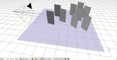
This method is easy to understand if you already worked with RealPeople objects in AutoCAD or 3D Max. Here are simple vertical planes that always look to the camera (Blender's very useful locked rotation constraint). On those planes are mapped trees from images with alpha channel. I won't describe how to do this because it's easy to find tutorials around on the net:
|
|
The image you map on these planes behaves like an object, project shadows, etc. If you make several copies of the plane, each one with a different tree image, you have the base for a little forest. The next step is placing the trees randomly on your project. Here again, we found a way to spare ourselves precious efforts... |
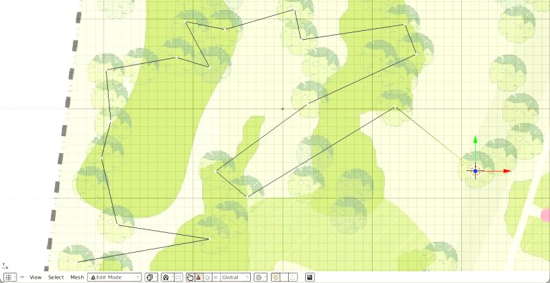
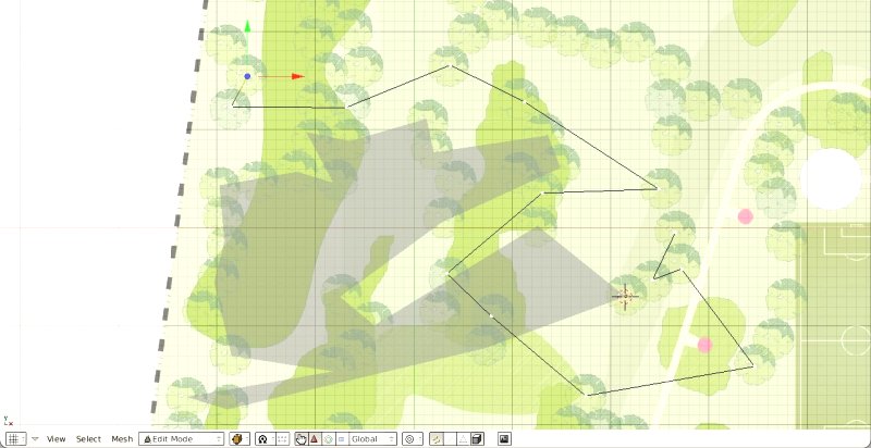
Again,
we used our project from AutoCAD, exported as a jpg image, and used
as a viewport background in Blender. On top of this, you draw
horizontal plane meshes putting points where there are trees, more or
less alternatively. Once you have several polygons, one for each tree
type, you just parent the tree to the polygon, hit duplivert and you
find yourself with a tree on each vertex of the polygon, all facing
the camera:
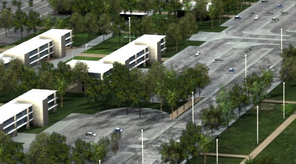
Once
your polygons are mounted, it's very easy to make the small
adjustments you'll certainly need (a tree in the middle of the
pathway, etc...). Just edit the mesh, and move the guilty vertex. The
bad side of this method (there is always one) is that the duplicated
tree looks at the camera, not every clone. This gave us problems when
the camera goes deep into the forests (look at the animation).
6. LIGHTING
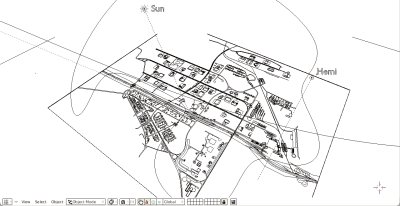
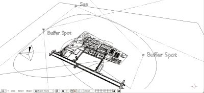
These 2 projects are so big that we didn´t bother much with lighting, since result would be very uniform anyway. In the Almoloya project, there is only a sun raytracing shadows and a hemi. In México, a sun throwing raytraced shadows and 2 spots with very soft buffered shadows to make that “fake radiosity” on the buildings walls (see here above).
|
|
|
7. THE “SAUCE”...
The final touch, the cerise sur le gateau, is all the “living things” you can put in the scene. This is the architect's oldest trick, but it always works: Put some people in your drawings and people will imagine themselves in it already. So we put people, parked cars, moving cars, streetlights, all things that you can propagate quickly through your scene to fill it without the need to model much or copy things one by one.
|
|
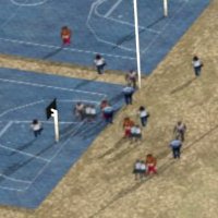
People They are only vertical planes facing the camera (Locked Track function) with an alpha-image mapped on it. Same technique as for the trees. |
|
|
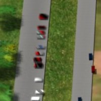
Parked Cars In Almoloya, they are made the same way as vegetation: One big plane covering the whole area, on it an alpha mask I made in the Gimp painting little black rectangles on a white layer. I then used a very dense Magic texture as color map, to make color variations between the cars. In Mexico, they are the usual low-poly car models you find everywhere on the net. |
|
|
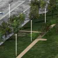
Streetlights These are a made of a simple extruded tube, dupliverted on a plane mesh. It is the same technique as the trees I described above. |
|
|
Moving Cars They are simple boxes following a closed path curve. One box is parented to the curve, then duplicated, each copy receiving a different time offset, so they move at same speed, but are on different positions on the path, giving that traffic look of several cars moving at same speed. |
8. ANIMATION
To animate the camera, we used the most basic technique, the camera follows a closed curve, so the last frame is the same as the first frame, to allow us to leave the video running endlessly behind us when making the (endless too...) presentation speech. The camera is parented to an empty, with a look-at constraint, so you get the same behaviour as a 3d Max camera: you get a target, that you can animate too.
That's it, more or less. Thes two projects were made in about two weeks each, one week for 2d project development, and one week for 3d and rendering (using all computers of the office, each animation rendered in about a weekend). I apologize if something in all this is unclear, but I guess it's not so important to follow these methods step by step, since every project asks for specific solutions. I hope I could at least show you how easy it is to use Blender for those big scale projects.
The big idea is always to find ways to stuff your scene with many objects, or at least give the impression of many objects, but keep the rendering time low, since rarely, in the architecture field, your client or even your boss has the smallest idea of the time needed to mount complex scenes, not to talk about rendering times. This added to the marvelous habit of changing the project continuously, will make you regreat it if you spend much time modelling.
Cheers
Yorik
