Ver 0.18 is coming along wonderfully!
Our gratitude as users, is difficult to express adequately. That is why always following along with the "Support for FreeCAD" page. If everyone helped a little (financially), that would be fantastic! I know I will try to do what I can !!!
FreeCAD BIM development news - December 2018
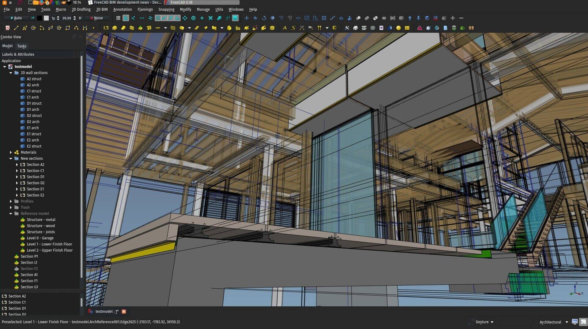
Hi all,
Finally to the last report about BIM development for FreeCAD for this year! This is already the 21st of these reports I'm writing (I'm keeping a copy of all of them on the wiki of the BIM workbench's github repo if you are interested).
It's been a pretty amazing journey so far, as always, thanks so much to you who is sponsoring this effort by donating on my Patreon, LiberaPay or Paypal accounts. At some point in time I'll need to setup a special credits page for the BIM Workbench where you'll all appear! And if you aren't, join us!
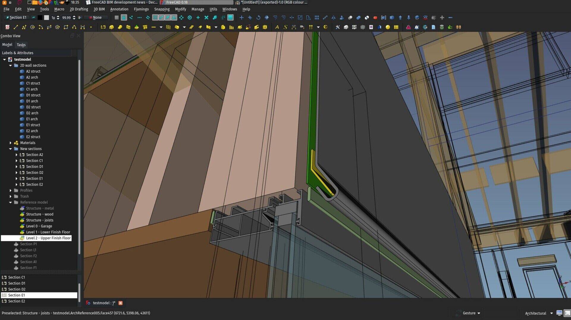
Most of the images shown in this report are from a project we are currently working on in the open with Ryan and Regis, with a pretty interesting FreeCAD/Revit workflow. Check the files there if you're interested!
The end-of-year balance
This year I really could spend quite a lot of hours working on FreeCAD and BIM tools, and I hope you'll agree with me that it rendered pretty decent results already. Really at this point I consider that we begin to have a very stable and powerful open-source BIM solution. I do almost all my architecture projects with it nowadays, and in many areas it already does better than the commercial alternatives we all know of. For example:
- No other BIM app as so many and so powerful modelling tools than FreeCAD (apart from Rhino maybe). Try modelling a car or a mouse or a cellphone in another BIM app... But it is the bread and butter of FreeCAD
- The BIM paradigm is very lightweight. You are not forced to use the wall tool to build walls. Walls don't need to be made in a certain way. You can use the wall tool to build a beam. Anything you model can be made into a wall, a beam or anything else. It's basically a thin layer of semantics on top of your model, or in other words, "agnostic" objects become "building-meaningful". This allow you to import almost any kind of 3D data into FreeCAD and use it in BIM models
- The parametric system of FreeCAD has become amazingly deep over the last year, and even if we don't have a visual programming interface like Dynamo or Grasshopper (yet!), the possibilities to plug one piece of data into another are wild
- The 3D view is comfortable enough to model directly in it. You have very fine control over what to turn on or off, you can see your working plane in the 3D view, etc. I'm always surprised at how much this is difficult in many BIM applications, while in non-BIM 3D modelling apps (SketchUp, Blender, 3DSMAx,...) it is absolutely normal
- All individual objects are easily searched and found, and can be named and grouped as you like, making the model extremely organizable, and maybe even more important, freely organizable (just like you decide how to organize your files and directories)
- This might be hard to believe, but comparing the IFC export of FreeCAD to other BIM apps, I dare to say in more and more cases we do far better. The model structure is more consistent (all organizing structures of FreeCAD such as levels, groups, assemblies/components are supported), and thanks to our friends at IfcOpenShell, when most other BIM apps desist and pitifully triangulate complex shapes, FreeCAD's IFC support can go pretty far and handle complex geometry with ease and faithfulness. It even supports NURBS surfaces, but as no other BIM application does so, I still couldn't test that very far.
- I won't talk about the advantages coming from being free and open-source, that wouldn't be fair game

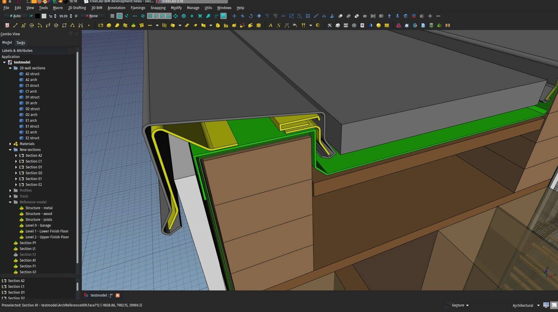
There are of course areas where we still lag seriously behind, for example:
User-friendliness: Since I began to work on the BIM workbench, I realized this is a far more complicated issue than we use to think. What is user-friendliness exactly? How do you measure it? Very often our notion of user-friendliness is based on how well we know an application. A Revit user will find Revit very user-friendly but think ArchiCAD is not, while an ArchiCAD user will think the contrary.
Another difficulty is that applications more universally considered user-friendly are very often so by limiting options. A very good example of this is TinkerCAD which really has a wonderfully intuitive interface, but try to do anything complex there, you will quickly reach the limit, or SketchUp, where you can gain power by adding plugins, but then you quickly loose the user-friendliness.
At this point I believe there is no miraculous recipe we can apply to instantly turn FreeCAD into a pleasure garden for the newcomer. One concept I really think could help us a lot, though, is making things progressive. You start with a simple set of concepts, and expand as your knowledge of the application grows. That's where I'm heading now with the BIM workbench.
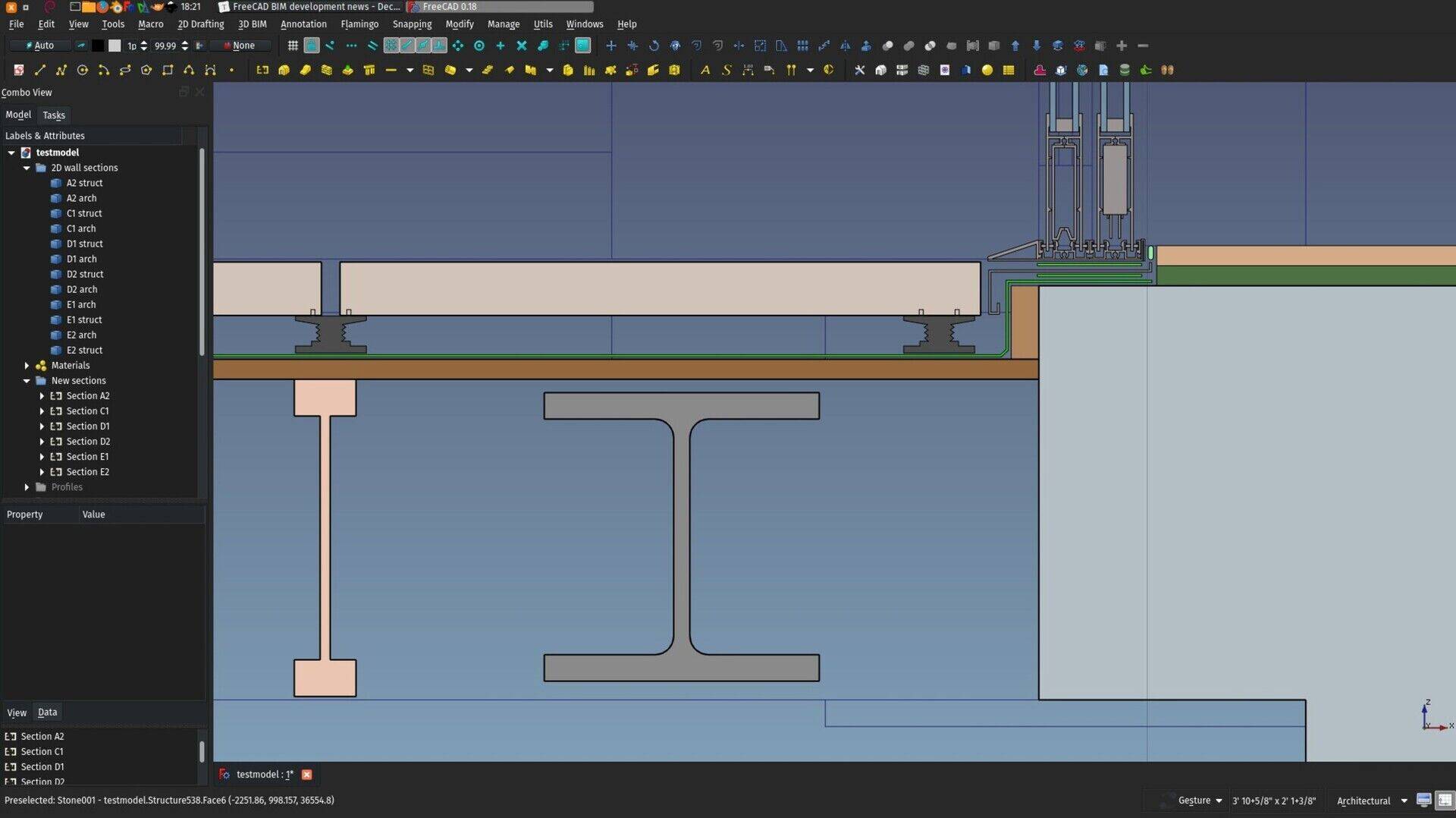
2D output: While we can produce BIM models of the same level of complexity and refinement as other BIM applications already, the same cannot be said of producing 2D drawings yet. The TechDraw workbench is mostly oriented towards mechanical design, and currently fails short to handle huge BIM models with all their details and annotations.
However, there are ways out of this, and I started experimenting with it already (see below).
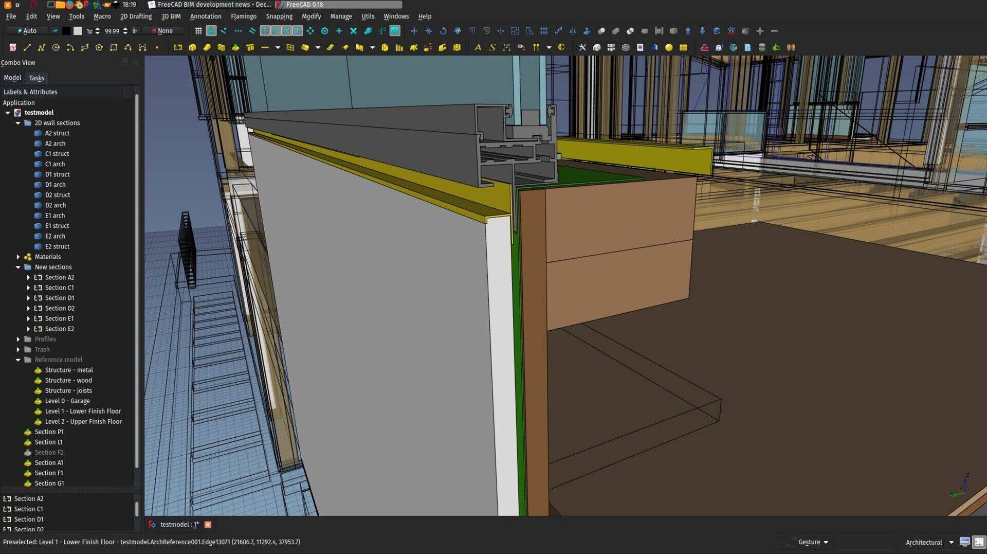
No video?
Nope, this month I'm officially in video-holiday! Next month we're back with one.
So, on with the enhancements I did this month. As FreeCAD is getting close to the 0.18 release and still in feature freeze mode, all the new features of this month are in the BIM workbench itself:
BIM library enhancements
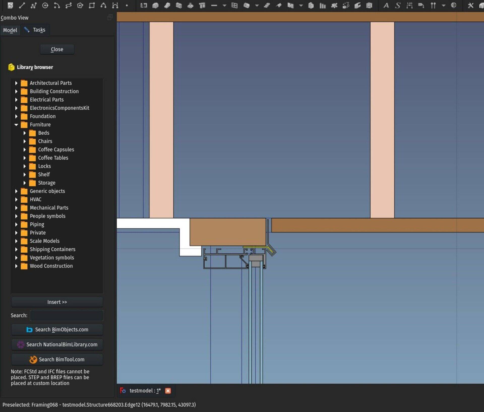
I have added a couple of enhancements to the BIM Library tool. It now supports IFC and SAT formats (this last one needs the CadExchanger add-on), and there is now a search function. There are also buttons that search on 3 well-known online resources of BIM objects, bimobject.com, the nationalbimlibrary.com and bimtool.com. This is mostly to test the usefulness so far. Most IFC models available on these websites are of awful quality (all curved surfaces triangulated, etc) so it didn't seem worth to me making a better integration, at least for now.
Personally, my best source of good quality models is still grabcad.com. If you limit results there for STEP/IGES files, you'll often get files of excellent quality, readily and perfectly importable into FreeCAD, and which are perfectly usable as BIM objects and appliances. BIM is not the main focus of grabcad, so the offering is limited, but there is more than enough of the basic stuff (basic furniture, sanitary/kitchen appliances, etc).
I'm not sure which direction to go with this tool now. What do you think? Integrate grabcad better than the others? Do some lobbying with the other BIM objects providers? Other ideas?
BIM material

The BIM workbench gained a brand-new material tool which I believe makes it much, much handier to work with materials. It has one main button that either offers to create a new material if nothing is selected, or, if any object with material support is selected, shows you a new, big, searchable material list, that you can operate fully from the keyboard (start typing, press arrows up and down, press enter) that makes it very quick to attribute materials to selected objects when you have a very big list of materials.
The materials also have icons that show their diffuse color. Later on I'll use this code to generate the tree icons of materials too.
From the same window, you can also create a new Material or Multimaterial.
BIM Views enhancements
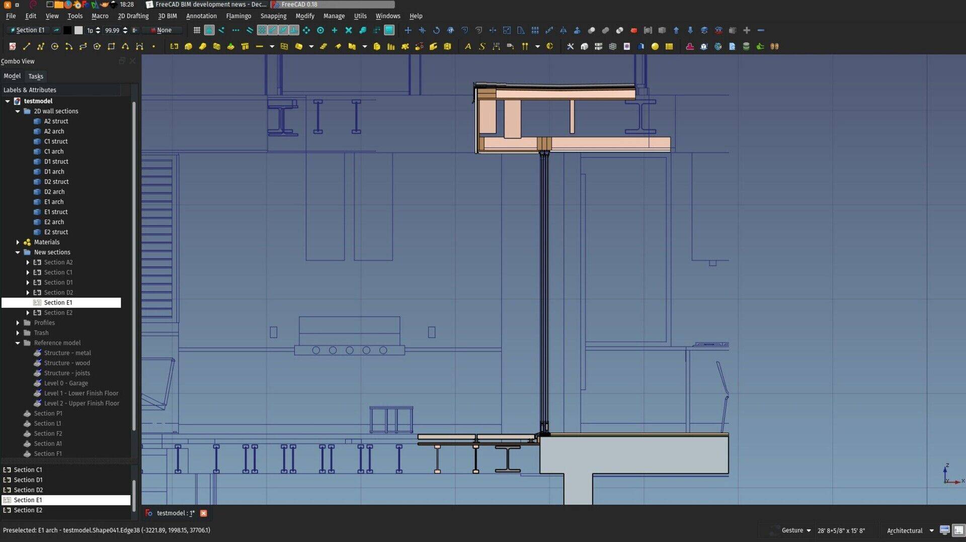
These are all improvements to the BIM Views tool. That tool is still in infancy, but the final aim is really to have a clean and easy way to manage all the different views and working planes of your document, and mimic, so to speak, how other BIM apps like Revit or ArchiCAD manage their views. The idea of this tool is basically that all the Building Parts and Working Plane proxies are shown there, so you don't need to search for them when they are buried deep inside the tree view. Double-clicking any of them will 1) set the working plane to it, and 2), if their "Restore View" (and provided you stored a view angle in them by right-clicking them in the tree view and storing the current view), restore the stored view.
So basically it works like views in other BIM apps: Double-click one, and find yourself looking into that view, with the working plane set where it needs to be. Building Parts and Working Plane Proxies now work almost identically, only the former can hold objects too.
Building Parts also now have a new "Auto Working Plane" property which, if set, keeps the working plane in "Auto" mode. So if you change the view to something else, the working plane will change to that view too automatically.
Responsive unit tag
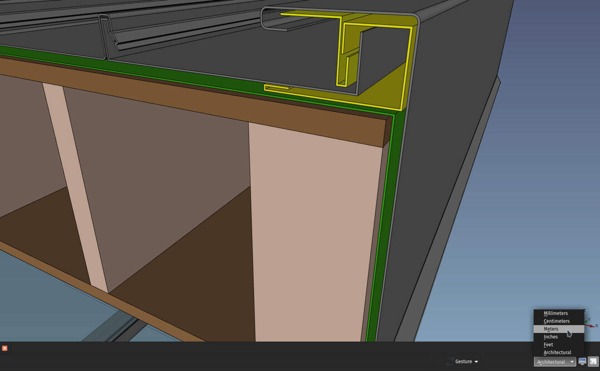
The unit indicator in the status bar is now properly clickable and sets the unit on the fly. No more back-and-forth to the preferences setting!
BIM sketch tool
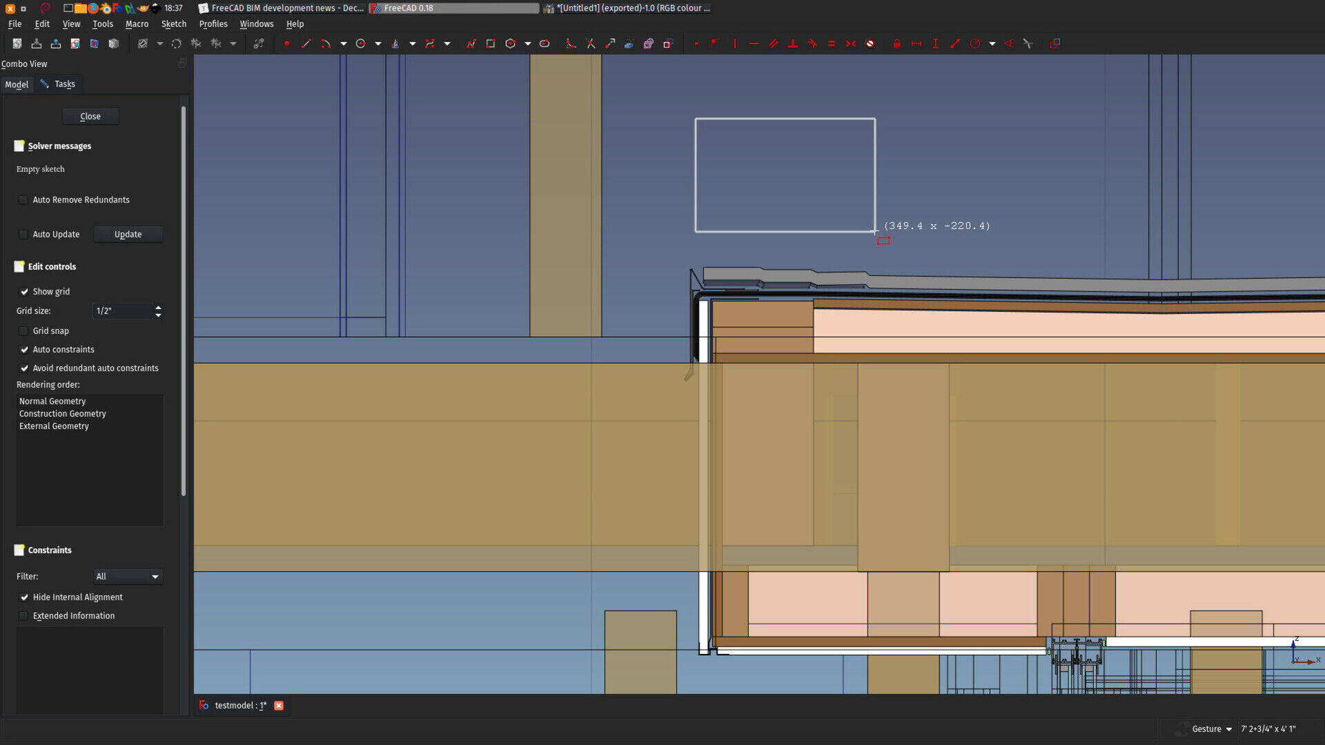
Instead of using the default sketch tool from the Sketcher workbench, the BIM workbench now has its own "new sketch" tool. The difference is very simple: New sketches start in the current working plane. So using sketches feels much more like Draft tools, and everything is much better integrated. Also, it doesn't change the view when entering sketch edit mode, so it escapes from the Sketcher's "introspective" mode, where when you enter the sketch, you sort of "forget everything else" to focus purely on the sketch. Here, you just draw sketches more seamlessly into your model.
If you prefer the standard behaviour, don't forget how easy it is to add a tool from another workbench (menu Tools -> Customize), but I found this really comfortable for BIM work, try it!
Status bar toggles
The BIM Views button has moved to the status bar, next to the button that shows/hides output panels, and both became toggle buttons (they have a pressed/non pressed state). They have similar default shortcuts (Ctrl+9 and Ctrl+0), I think it makes much more sense.. The BIM Views tool is not really a management tool, it makes more sense here IMHO.
People and tree symbols
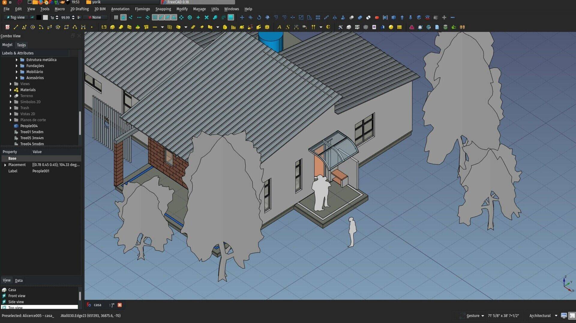
I added a series of simple 2D symbols to the Parts Library (installable via the Addons manager) that look like those found in other apps like SketchUp or BricsCAD shape (which is quite interesting BTW, try it, it's free and multiplatform, a kind of "solid modelling SketchUp". It still crashes often and there is no easy way to import its results into FreeCAD, but it is definitely an interesting thing). Although they are 2D, they are meant to be used in 3D models. It's just that they are symbolic instead of fully modelled. But for that reason, they are very lightweight. And I kind of like that aspect...
If you think of anything else that would be useful to have modelled that way, let me know!
Coin-based 2D view experiments
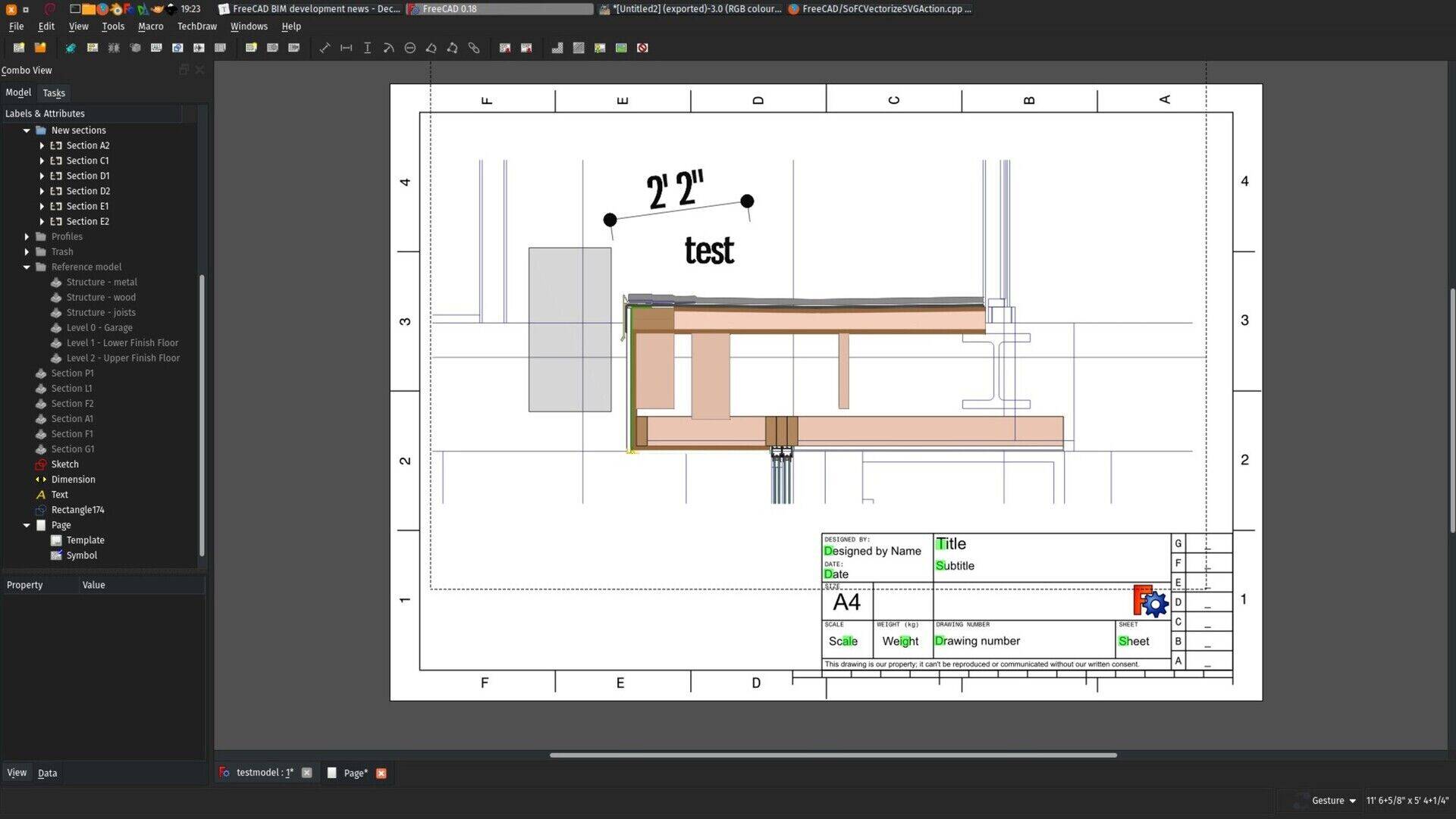
As stated above, one of the areas of FreeCAD that really lags behind for BIM use, is producing complex 2D documents such as construction documents. The TechDraw, although pretty powerful already, is more focused on mechanical design, which are typically much smaller models.
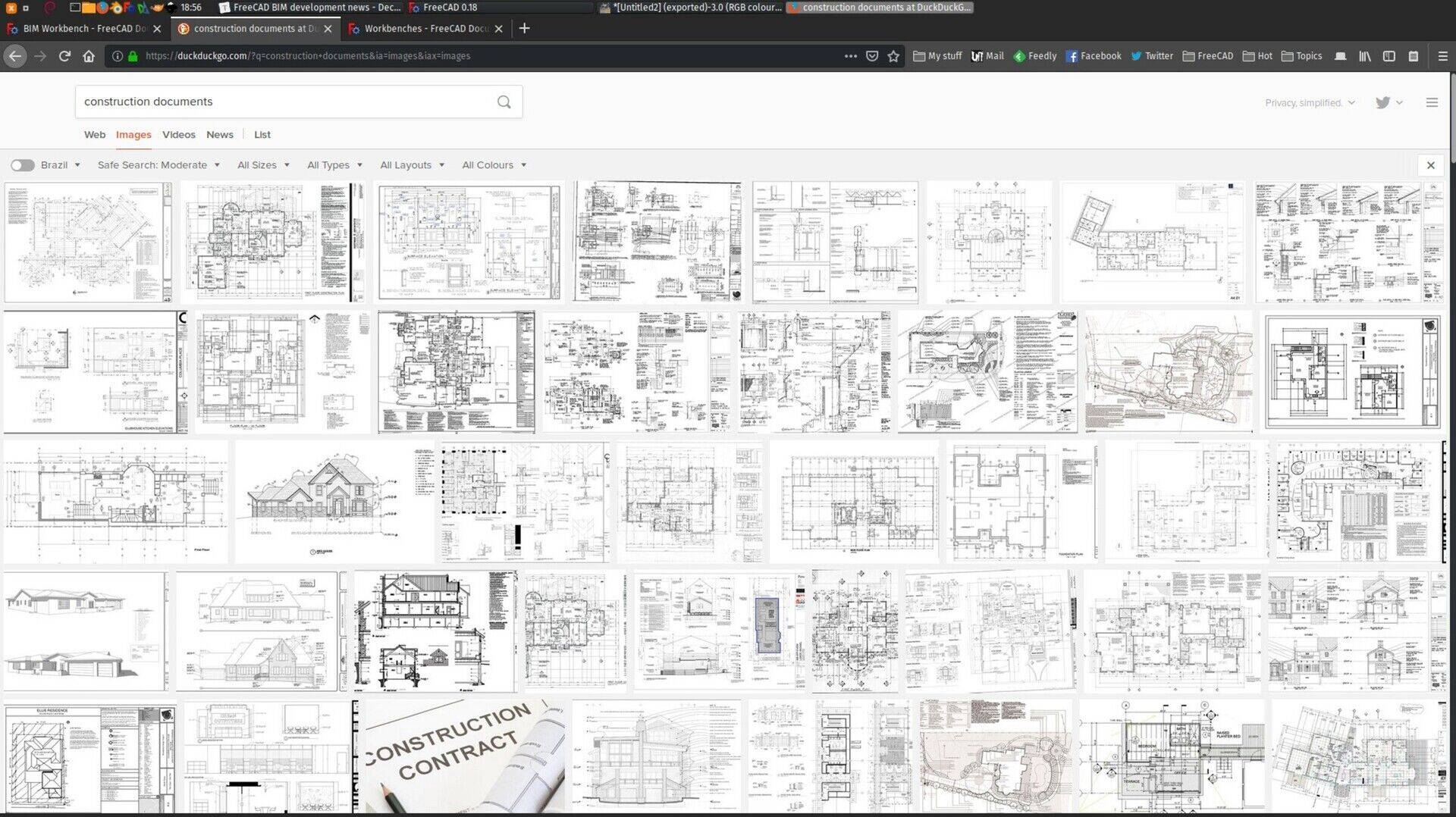
There are several problems there for us who work with BIM: One is the time that it takes to produce a 2D view of a large model, because there are several heavyweight Boolean operations involved, and the 2D drawing itself is done by OpenCasCade (the geometry engine of FreeCAD) itself, on which we have no control, another is that, as you can see on the image above, there are usually many things on such a drawing that is not geometry but annotations: Texts, dimensions, labels, symbols, etc.
All this is old story, I've written a lot about this on this blog already.
But I've recently found one more hidden gem inside FreeCAD: the ability to export very faithful vector graphics from the 3D view of FreeCAD. There is a quite interesting system provided by Coin3D, the display library used by the FreeCAD 3D view, that walks through the different entities (lines, triangles,..) displayed on screen and allow you to do something with each, such as exporting them as SVG. It already works amazingly well, you can try it simply by issuing the following command in the FreeCAD python console:
FreeCADGui.ActiveDocument.ActiveView.saveVectorGraphic("/path/to/some/filename.svg")
It need a bit more work, for example to support line thickness better, of image textures, but it works already amazingly well and is blind fast and precise. And the algorithm could probably easily be adapted to produce QGraphics entities that are used in TechDraw, and therefore obtain a result where dimensions and pattern fills work.
We could do quite a lot of annotation work directly inside the 3D view, this works quite well already, and we could have blazing fast, virtually unlimited amount of 2D views inside a FreeCAD document.
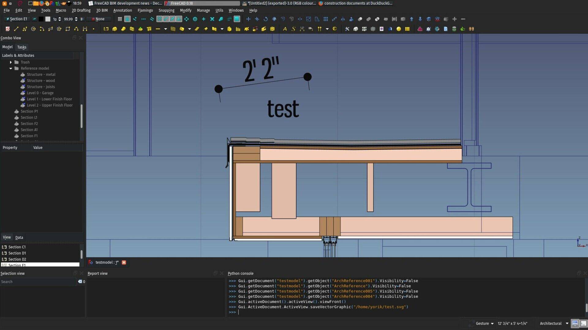
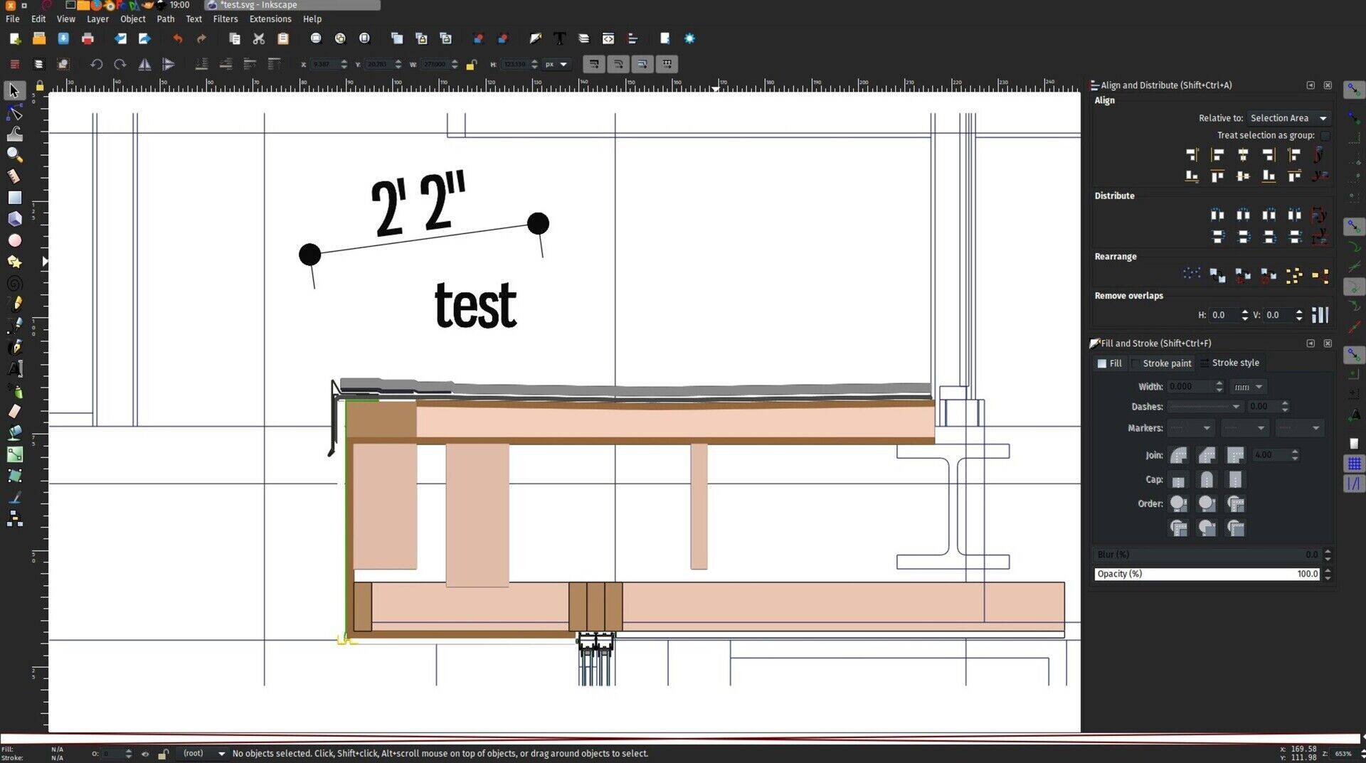
All this needs some thought and work, but it seems to me a more than interesting path to go. There are several issues to solve, for example the scaling (the output is dependent on the view size and proportions), and also the fact that currently the view needs to be displayed on screen for this to work, but these problems certainly have several possible solutions.
Stretch tool enhancements
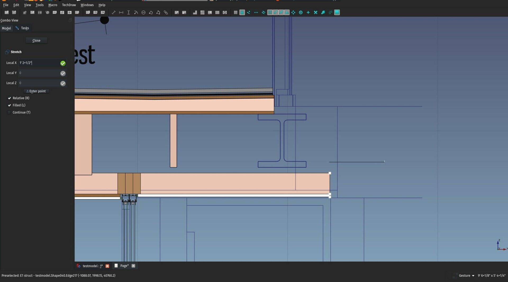
This is I think the most exciting change of this month. The Stretch tool, that so far only worked with 2D objects, now works with BIM objects as well, provided they are based on a 2D object. This seems like a small change, but it is actually a massive step in direction to direct modelling: BIM objects can now be deformed and stretched graphically.
So far this will only apply to the 2D shape that is used as a profile or baseline of a BIM object, so it cannot be used for example to change the extrusion height of an object, but we'll get there in time.
This is not really like Revit, more like old-school AutoCAD, when you had no object handles, but it seems to work amazingly well, and if it proves solid (I think it is), we can extend that a lot, to other tools too such as Draft Edit, and slowly get there.
BIM update mechanism
The BIM workbench now has a mechanism that will check for your installed version against the most recent one on GitHub, and pop up a notification if an update is available. You need the python-git package installed for this to work, but it's on my to-do list to make this work regardless of this package (and actually extend that to all add-ons).
BIM WorkingPlane View
There is now also a new view shortcut, (key 9 or menu Utils->Working Plane view) that sets the view to the current working plane or, if the BIM Views window is open, to the last item double-clicked there. So you can now pretty easily navigate between your current Building Part and other standard views such as Front, Top, etc.. using the keyboard only.
Thar's it for this month, thanks for reading until here, I wish all of you a happy new year, and see you next month!
Cheers
Yorik
PS - Only recently I realized that I never put the appropriate captions on the images of these articles... If you are blind, I really apologize, from now on that will be done with care.


FreeCAD BIM development news - November 2018

Hi all,
This is the November edition of our monthly report about the development of BIM tools for FreeCAD. As you know already if you read last month's report, we are (increasingly) busy preparing FreeCAD for its next 0.18 release, which is scheduled to happen before the end of this month/year. So far so good, we are busy ironing out the last bugs and getting everything ready.
By the way, one of the areas that always needs a lot of help from the community of FreeCAD users, is translation. With each release, we achieve a bigger number of languages in which FreeCAD is fully translated. This year, we have many that are above 90% already, and a couple of others that lag behind, that would really deserve some care. Do you know any of the languages on our translations framework? Please help! Just create yourself an account there and you are ready to go. No need to compromise yourself to reach any goal, if you just have 5 minutes and can translate 5 sentences, you will already have helped the project a lot! (And if you reach 500 sentences, you will have your name in the credits in FreeCAD -> Help -> About FreeCAD  )
)
Last month I announced I would spend more time on the BIM workbench itself this month, as it is not tied to the pre-release "feature freeze" in which FreeCAD is at the moment. I did that, but I also underestimated the amount of bug-fixing needed in FreeCAD, so I ended up still spending a lot of time on FreeCAD bug fixing. In any case, one thing is as important as the other, and I think with this release the whole BIM ecosystem inside FreeCAD is reaching a level of maturity and stability that we never had before, and that it is becoming ready to enter the big player's courtyard.
As always, many, many thanks to all of you who contributed to this effort by donating money on Patreon, Liberapay or Paypal so I can spend more time working on FreeCAD. Next month, since it will be the last report of 2018, I'll do a small recap of these nearly two years of "campaign", it has been steadily increasing over the time, and so far it is a really motivating and, I hope, productive experience.
So, enough boring bla-bla already, let's go to what interests us:
The video: Expressions
This month's video is about the expressions engine of FreeCAD:
BIM Interface changes

This is a small change, but curiously something I never really gave some thought before. As I am working more on the User Experience (UX) side of things with the BIM workbench, these questions take more importance. Until now, I tried to fit all the new interface panels inside the Task panel of FreeCAD. This is the good old idea that interface elements should not block your 3D view, and stop you from working. However, some tasks do require you to stop working and work on the task only. These should not be squeezed into the sidebar but get a larger dialog that occupies the central part of your screen. So the Project setup dialog now has a nicer and more comfortable dialog and it works much better.
The other BIM tools from the Manage menu should, I think, stay in the Task area, as they allow you to interact with the contents of the model. I think we have a good rule from now on to decide what should be in the Task area and what should get its own separate, blocking dialog. I will try to assess which areas of FreeCAD are not following this rule correctly.
BIM Tutorial

This was one of the first ideas I had for the BIM workbench, and the system is now implemented and running, although the tutorial itself is still incomplete. The concept is largely used in games: After you install it and start a new game, you are often offered to take a tutorial first, to familiarize with how the game works. That tutorial is often itself the first chapter of the game, so you play a first chapter that is specially designed to help you learn what needs to be learned, and you are guided through it by tips boxes, explanations, small "goals" you need to achieve, etc.
I find that brilliant, very different than a video or text tutorial. You are already playing, and the game explains you how to play it. After you finish the tutorial chapter, you are on your way.
The idea here is to do as much as possible the same: Have a tutorial that "unfolds" right inside your FreeCAD window, and that guides you through a series of steps designed to show you how things work. Each page of the tutorial explains you something, and has goals to be achieved.

The tutorial is entirely written on the FreeCAD wiki, so it is easy to get fixed and bettered by community members. Each goal has a simple, one-line python test, that returns True or False. I hope this will become a killer feature that no other BIM application has, and might also be of a big help to overcome the steep learning curve of FreeCAD.
Units chooser in status bar

You can now change the working units on-the-fly, directly in the status bar.
BIM Documentation

The BIM workbench documentation is finally complete. Although many of the tools can still evolve, we now have an up-to-date documentation, which is a very fundamental piece of the game too.
Parity table

I also started a parity table which I believe will be a very precious resource to learn FreeCAD and its BIM workbench when coming from another application. Please help me to complete it with other concepts and applications!
Task Watchers

The BIM workbench now has what we in FreeCAD call Task Watchers, which takes place inside the Task panel when no command is active. These watchers can change according to the context, so we can really use them to guide the user through logical sequences of actions. At the moment, they will simply display creation tools when no object is selected, and modification tools when something is selected. However, I plan to refine that when we see opportunities for it.
Revit compatibility

I also spent some time fixing a few issues in the IFC importer and exporter, and we begin to get a satisfying experience when exchanging models between Revit and FreeCAD. It is now possible to model in FreeCAD with a reliable 100% of your exported objects appearing correctly in Revit and being editable, by 1) using only extrusions (Part Extrude, Arch Structure or Arch Wall) and 2) Setting the IFC role of all exported objects to "Undefined", which will export them as IfcBuildingElementProxy, which imports into Revit as Generic Components. This is not mandatory, of course, all IFC types are supported, but the reason is that some other types have additional rules that sometimes override the way the object is stored inside the IFC file. To say it another way, if some object doesn't appear correctly in Revit, set its IFC role to "Undefined" in FreeCAD. Although not ideal (yet), at least it is reliable.
That's it for this month, I'm not listing here the small bugfixes and polishes I've been doing a bit everywhere, be sure to check the commit log of FreeCAD and the BIM workbench if you are interested in the details. Thanks for reading!
Cheers
Yorik


Can you a share a little insight? When we could expect to see dimensions for archsections in the techdraw workbench will arrive?


Funciona sim, o único problema é que quando você troca para cut faces, o objeto Shape2Dview fica no plano de corte, e não no "chão". Você tem que mudar a propriedade "In Place" para False (ou mover ele manualmente, claro).
Abraços
gostaria de saber se é possível utilizar a ferramenta cut faces em uma seção vertical (corte).
Só consigo utilizar em seção horizontal (planta) !
grande abraço!
FreeCAD BIM development news - October 2018
Hi all,
High time for a new article about what I've been doing this month with FreeCAD related to BIM development. Sorry for being late! This month again, there are not many new features, basically because 1) I've been to the Google Summer of Code mentors summit at Google, in San Francisco Bay Area, and 2) FreeCAD has entered "feature-freeze mode", that is, a special time scheduled before an official release, where everybody agrees to not introduce any new feature (which might always introduce new bugs), and instead, solve all possible bugs to make the release as bug-free as possible.
That is no less important, of course. Bug fixing is an important part of the development cycle, even if less enjoyable. Developers always prefer to code new stuff, which is far more exciting, and, as any other human being, tend to leave the boring stuff for later  So it's good to have a time where we force ourselves to concentrate on bugs. Also, it makes it much more enjoyable and motivating when your friends are also busy fixing bugs, it turns the whole thing into a kind of game.
Once again, thanks a lot to all of you who contribute to this whole effort by sponsoring me on Patreon or Liberapay or who directly sent some bucks on my PayPal account. Sorry for leaving you probably hungry for new features this month, but I'm sure everybody understands the importance and necessity of this bug-fixing phase. Since the BIM workbench is not part of the FreeCAD code base, though, it is also not part of the feature freeze. So expect some new stuff there in the coming months anyway, as soon as I get the bulk of the bug-fixing effort done.
0.18 Release
The plan is to have a new release of FreeCAD ready for the end of this year or early 2019, in time for the next Debian freeze cycle (they also have one, during which they don't accept any new package). This is important because if we get the new version of FreeCAD into Debian in time, it will cascade back on Ubuntu and all other derivative distributions such as Mint or Elementary, and all the next versions of these distributions will automatically get that new version.
This release will not bring a very big amount of new features, but rather be dedicated to stability. We've been busy this year with porting FreeCAD to the latest versions of Python (Python3) and Qt (Qt5). This makes FreeCAD basically future-proof for a reasonable time. Not that FreeCAD still supports Python2 and Qt4, so it can still safely be built on older platforms. We will probably continue to support these until they get really obsolete.
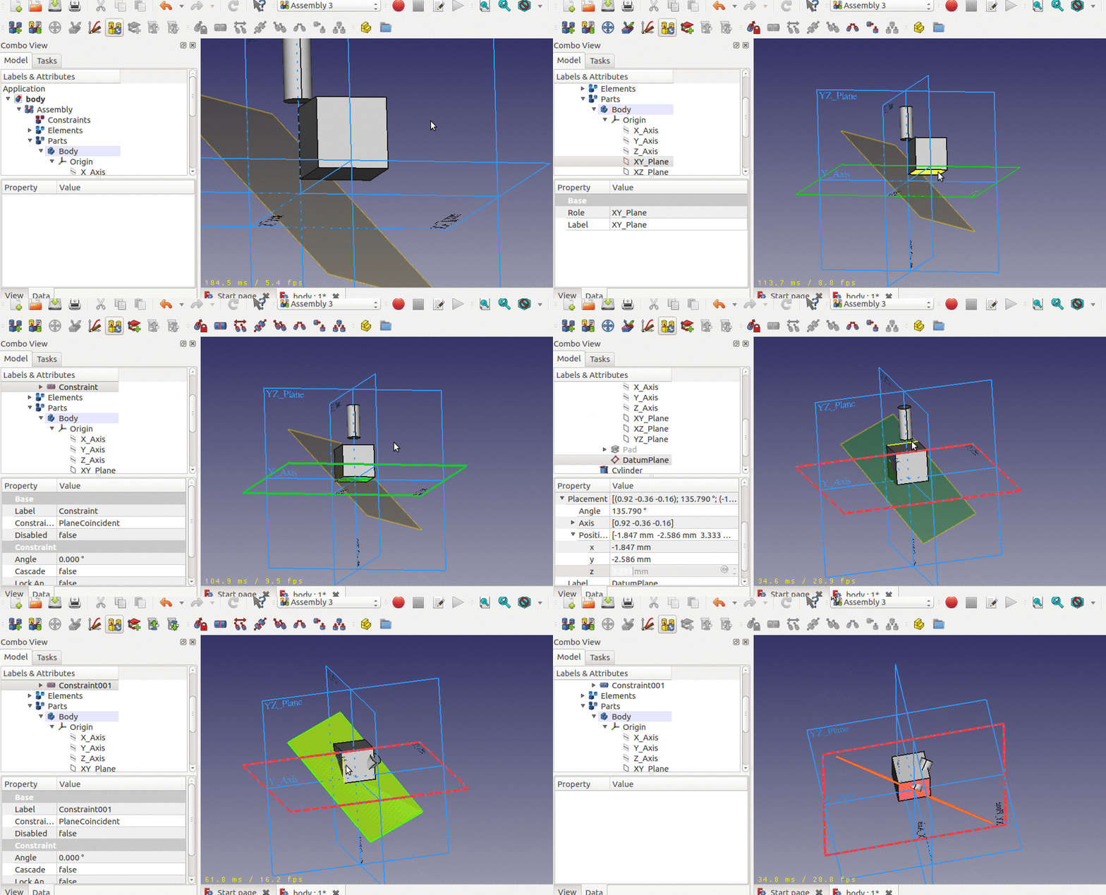
Another reason to make this release is that we have big things coming in. The new Assembly3 workbench is close to completion, but it represents a big change to the FreeCAD code, and introduces a lot of new bugs. However, while it is not merged into the main FreeCAD code, very few people actually test it, and therefore bugs are slow to get spotted. And the Assembly3 code is so huge that it has become very difficult to assess and split into more easily manageable parts. So we are pondering if it would not be best to merge it and let the bugs happen, and fix them as they come. In any case, for that, we need to have an official release just before, so people can stay with a stable version until things calm down.
By the way, if you haven't seen it, we now also have a third way to makes assemblies in FreeCAD, with a new plugin workbench called A2Plus which is now an official FreeCAD add-on](https://github.com/kbwbe/A2plus) that can be installed via the Addons Manager. So now we are starting to have a whole family of solutions to deal with assemblies in FreeCAD. Choose what suits you best!
The video
This month's video is about producing 2D drawings from your model, and placing dimensions, hatches and annotations.
Google Summer of Code Mentors Meeting
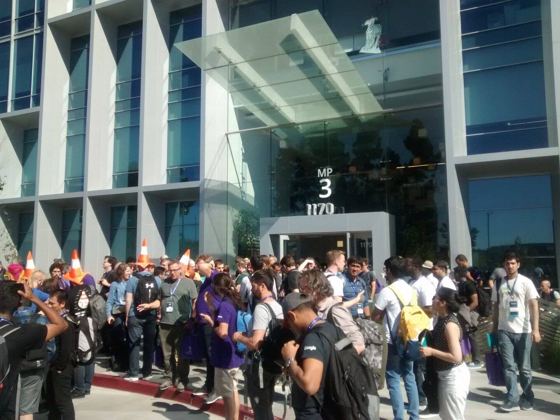
As I mentioned above, I've this year again attended the GSOC Mentors Meeting, which happened at Google headquarters in California. Since we participated to the GSOC program this year again, together with our FOSS CAD friends, we earned a couple of slots to go to California. This year, I went to represent FreeCAD, together with Sean Morrison and Daniel Rossberg from BRL-CAD.
The mentors summit is an incredible experience, unlike any other open-source-oriented event I've been lucky to go. A part of the Google campus is open during one weekend, to receive around 300 developers from the whole world. There is plenty to eat, drink, do and watch at any time of day and night, plenty of goodies for you to grab, and they provide several spaces for people to gather and discuss what they like. That's basically it. And it works amazingly. You end up talking a lot to everybody else, contacts are made, brains work, ideas are discussed, projects get born.
This year I had pretty long discussions with both Sean and Daniel, about two interesting subjects: Integration of FreeCAD and BRL-CAD, and a general effort to do more integration with all other FOSS CAD projects.
The BRL-CAD and FreeCAD integration is something we've been discussing with Sean for some time: BRL-CAD is in need of a better modelling interface, which FreeCAD can provide, and on the other hand the BRL-CAD system is a very powerful modelling engine, and it would only serve FreeCAD to make use of it. Besides, FreeCAD being so modular and extensible, we made an habit to try to plug anything we can into it..
We are still thinking as to how this integration would/could happen, but it would likely be on the form of an additional FreeCAD workbench/addon, a bit like the OpenSCAD workbench. BRL-CAD has a nice C++ API, to which Daniel is one of the main contributors, which is very likely what we would use. The aim would be first to be able to use FreeCAD to model and save the result as a BRL-CAD file, then see all we can get from this that could benefit FreeCAD. One of the big advantages of BRL-CAD is its capacity to manage extremely large models. And it can do all the important parts that we need in FreeCAD: Geometry calculations and triangulation.
The other idea is actually a series of ideas we have been discussing, to encourage the interaction between all the different FOSS CAD projects out there, such as LibreCAD, STEPcode,OpenSCAD, LinuxCNC ro Slic3r. There are many others specially in the BIM area (IfcOpenShell, IfcPlusPlus or BIMServer for example), that could be interested in this as well. Unlike the commercial world, where each similar application to yours is seen as a concurrent, that you should try to beat (or buy, or kill, or, even better, both), in the open-source world we can help each other, and help users with a family of tools that work well with each other. Each individual application benefits from this, as it integrates and can count on a more solid ecosystem.
Our ideas ranged from a common forum, structures to be able to collect and redistribute donations, definition and sponsoring of common projects, etc. There is much to be defined and done there yet, but we now have several people committed to make this happen. As soon as we have something ready, you'll be the first to know 
Ah, as usual, there was an impressive table of chocolates that everybody brought from all corners of the world. I had also brought a load of FreeCAD stickers (very poor ones that I made at the last minute, will do a new batch of better quality ASAP) that got entirely distributed. Quite a lot of people know FreeCAD nowadays!

Arch Reference improvements
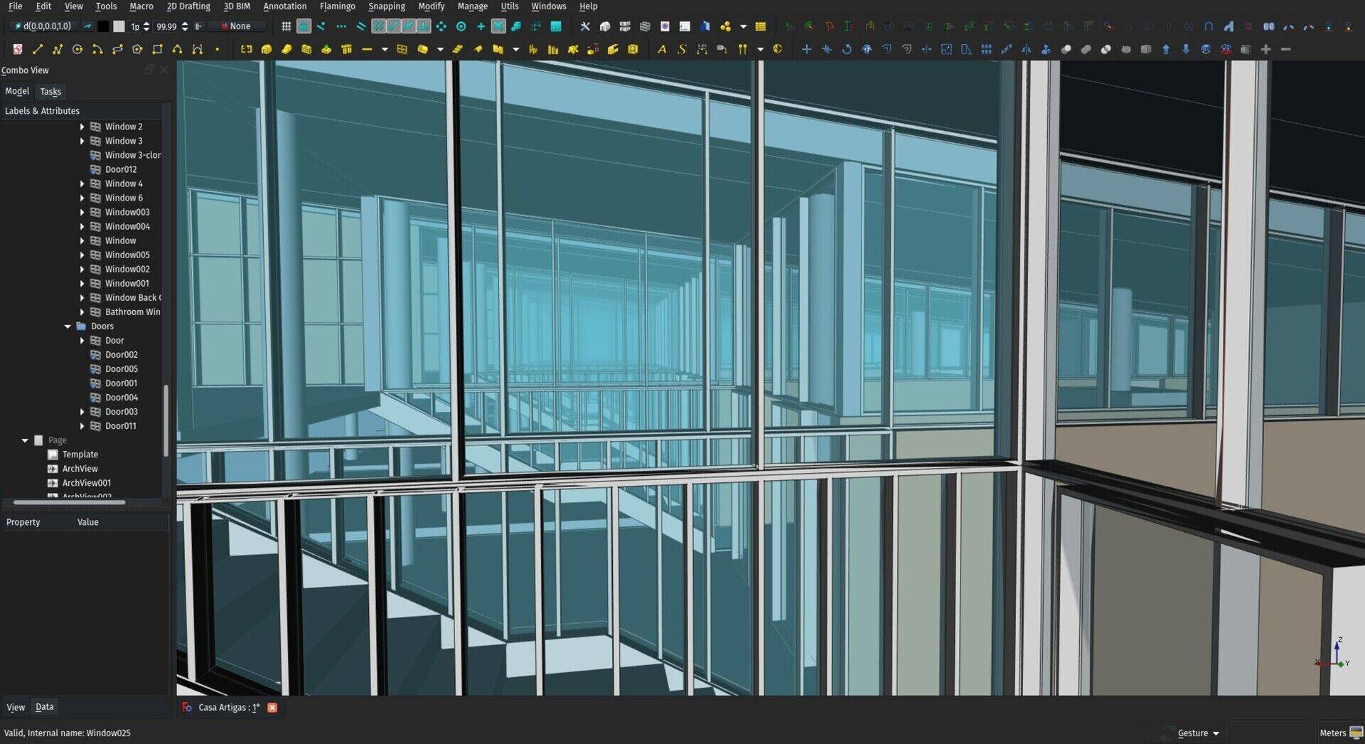
Besides this, I've also added another feature to the Arch Reference, which is the support for colors. When reading an object that has individual face colors defined, the Reference object will adopt those colors (and, if its UpdateColors property is set, will keep those in sync if the base file changes). The Arch BuildingPart has also be updated to store the colors of its children, so from now on you can create a whole BuildingPart made of several objects, reference it in another file, and have its aspect look exactly like in the referenced file.
I am already experimenting with the next step, which is to introduce a "lightweight" mode, which will allow us to work with way larger models. This will probably only be merged after the 0.18 release, but we'll make sure to have everything ready by then.
That's it for this month, expect more focus on the BIM workbench itself next month, thanks for reading, and thanks again to everybody who supports this effort!
Cheers
Yorik


There is not much in the field of electrical planning at the moment. But I believe everything is there to start, it would be more a matter of creating all the parametric objects that are needed for electrical design. Why not join the community at https://forum.freecadweb.org and start a discussion about it?
 Others may be interested in joining efforts...
where can I see more of Electrical-planing with Freecad?
is it the BIM ready..means the e-plug is a ifc from some company or a exchangeable selfmade one. even the e-cable is ifc?
I need to go seriously into the design with FreeCAd. Looks like it is not long away to a professionel tool. Thanks for that.
Lukas
Yes Yorik, the stndard name is "assets", I mean, not?

Very useful feedback, thanks!! I could indeed do a longer one from time to time...
FreeCAD BIM development news - September 2018
Hi folks,
Time for one more of our monthly posts about the development of BIM tools for FreeCAD. This month unfortunately, since I was taking some holiday, travelling (and sketching) for the biggest part of the month, I have less new stuff than usual to show. To compensate, I tried a longer and more detailed video. Looking back at it, I think this is a bit too long, though, so next time I'll get back to a shorter format.
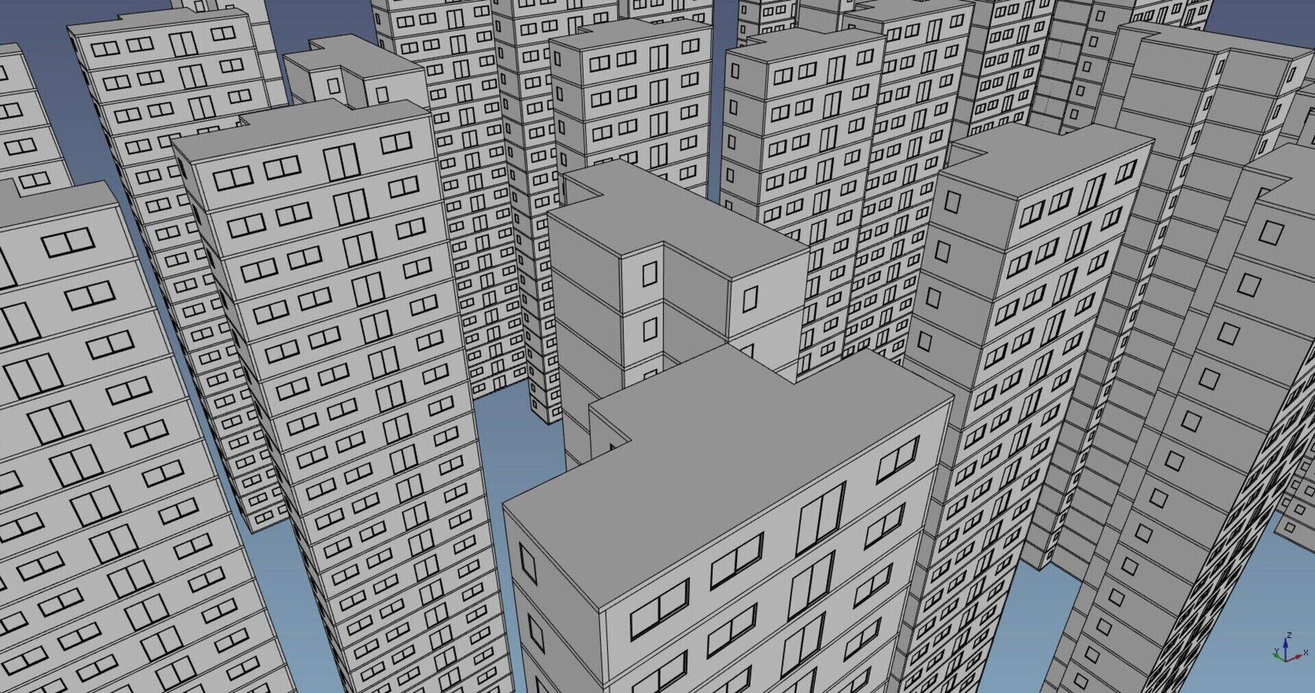
As usual, many thanks to everybody who is backing me up on Patreon, Liberapay, or donated directly to my Paypal account, this is a really amazing experience, I hope you guys feel as thrilled as I do about the progresses we're doing here, each month we have a new layer of paint on the wall, and it begins to form a very solid and coherent compound. I sincerely think some parts of the job are now almost done (basically, BIM modelling itself) and already work as well or even better than many commercial BIM applications. What I am going to concentrate more and more on, in the next months, is the 2D output, ie. how to generate good quality drawings from our BIM models.
I have several threads to explore there, one being of course TechDraw, where we need to optimize things to be able to work with larger models, and integrate better the native TechDraw tools with BIM models, and another thread is the 3D view itself, in order to obtain a more "WYSIWYG" (What You See Is What You Get) workflow, that is, have the 3D view really give you good and useful 2D views of your model. Finally, see how we can tie both these threads. Our OpenInventor-based 3D view has several tools for offline rendering, that is, produce a "copy" of the 3D view that can be used for other purposes, such as saving an image. This could offer us a blind-fast way to generate 2D documents, and could be a very interesting path to explore too.
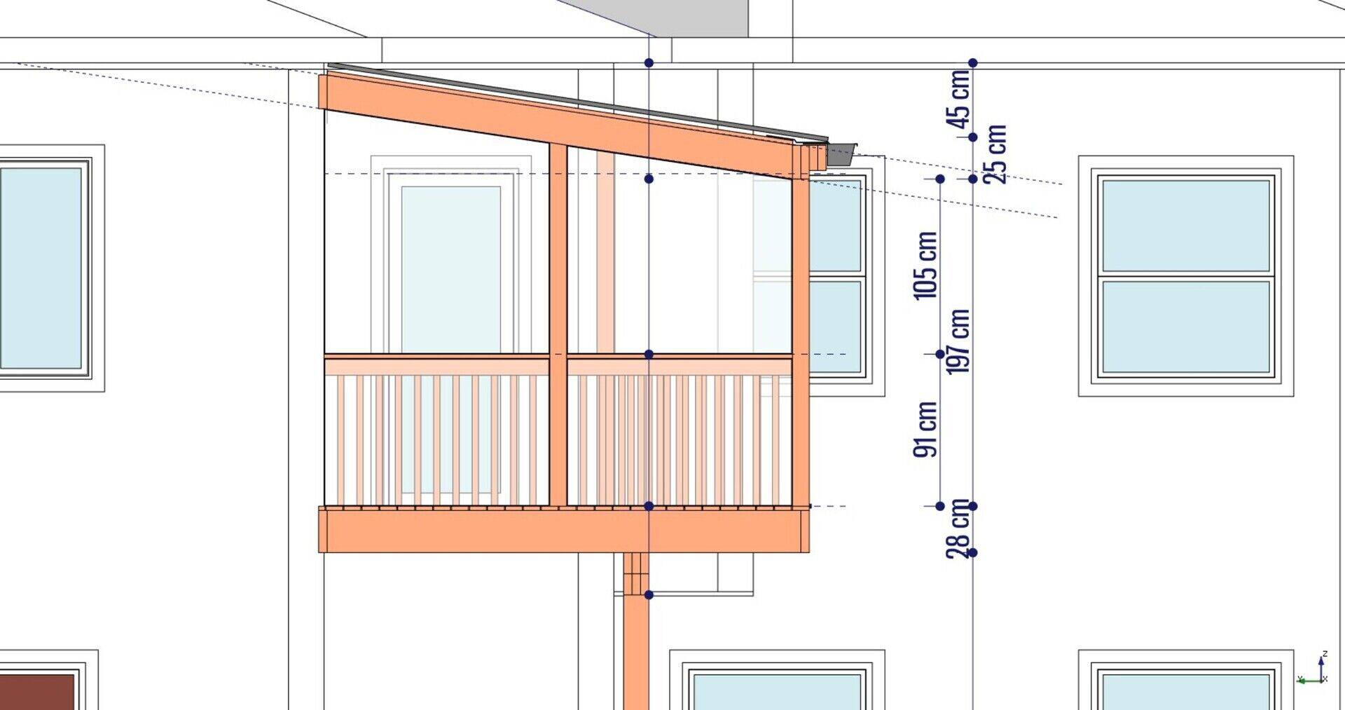
The video
This month the video is a generic tutorial that shows how to get started with BIM modelling in FreeCAD:
BIM workbench documentation
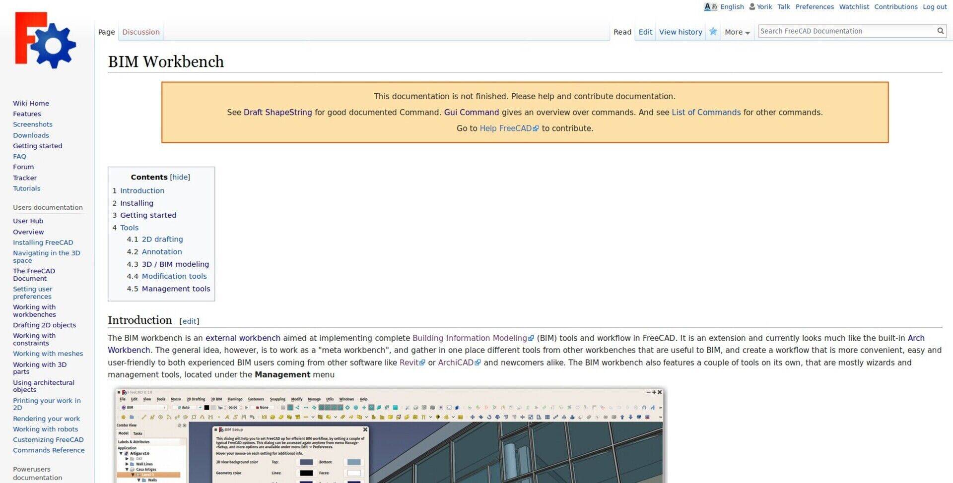
I've also started working on the documentation of the BIM workbench. As you know, the main effort behind the BIM workbench is to offer a good user experience. This is therefore a very important point. There is still some work to do, but it is there already and usable. It is also something I wanted to do to advocate other Addon workbench developers to use the FreeCAD wiki to write their documentation. The new Start workbench, that has landed in FreeCAD last month, will display links to specific workbench pages on the wiki, so this would be very useful.
past development news articles on github
I also gathered all the development news articles I wrote so far on the github page of the BIM workbench, inside the "wiki" section. Some might find them easier to find and read there than on my blog...
External references
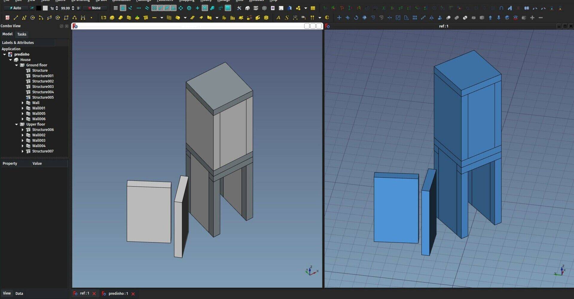
The big, new feature that has landed this month in Arch (and therefore BIM) workbench is the new [External Reference] tool. It basically works like an Xref in AutoCAD, or File Link in Revit (I'm not sure how it's called in other apps...). To resume, it allows to include the contents of one file in another. If the contents of the first file change, what's included in the second file changes too.
Working with reference files has a lot of advantages: One person can work on a part of a model, while others can work on other parts, and everyone can keep working on a separate file. Or you can split big files into smaller, more manageable chunks.
In FreeCAD, it has also a big extra advantage: Like in most parametric modellers, having a lot of individual objects in your model document makes FreeCAD run significantly slower. The 3D view of FreeCAD is capable of rendering several millions of faces without much slowdown (yes we tested), and the OpenCasCade engine is actually very efficient at managing very complex geometry. The problem is the logic. Each new document object created inserts a load of relationships with other parts of FreeCAD, because there are many mechanisms that must run every time you touch an object. Often, these mechanisms need to scan all the objects of the model.
It is interesting to compare this with games. A couple of years ago, the biggest part of the CPU computing occuring when you were playing a modern, resource-intensive game, was to compute the 3D graphics. Now, in some recent games like Kingdom Come (my favourite of the moment), the Artificial Intelligence uses more computing power than the 3D rendering! This is because each character in the game has its own "program" running, all interacting with each other, creating exponentially long chains of computation. Basically the same happens in FreeCAD. Such is the price of parametricism, that you'll have to pay one day, mister Schumacher! (Architects joke, don't worry about it)
By using reference files (I'm not sure the name is really good... Any other idea?) in FreeCAD, you can include the whole content of one file (several objects) as one object in the host file. This reduces dramatically computing time, and allow us to work with increasingly bigger models.
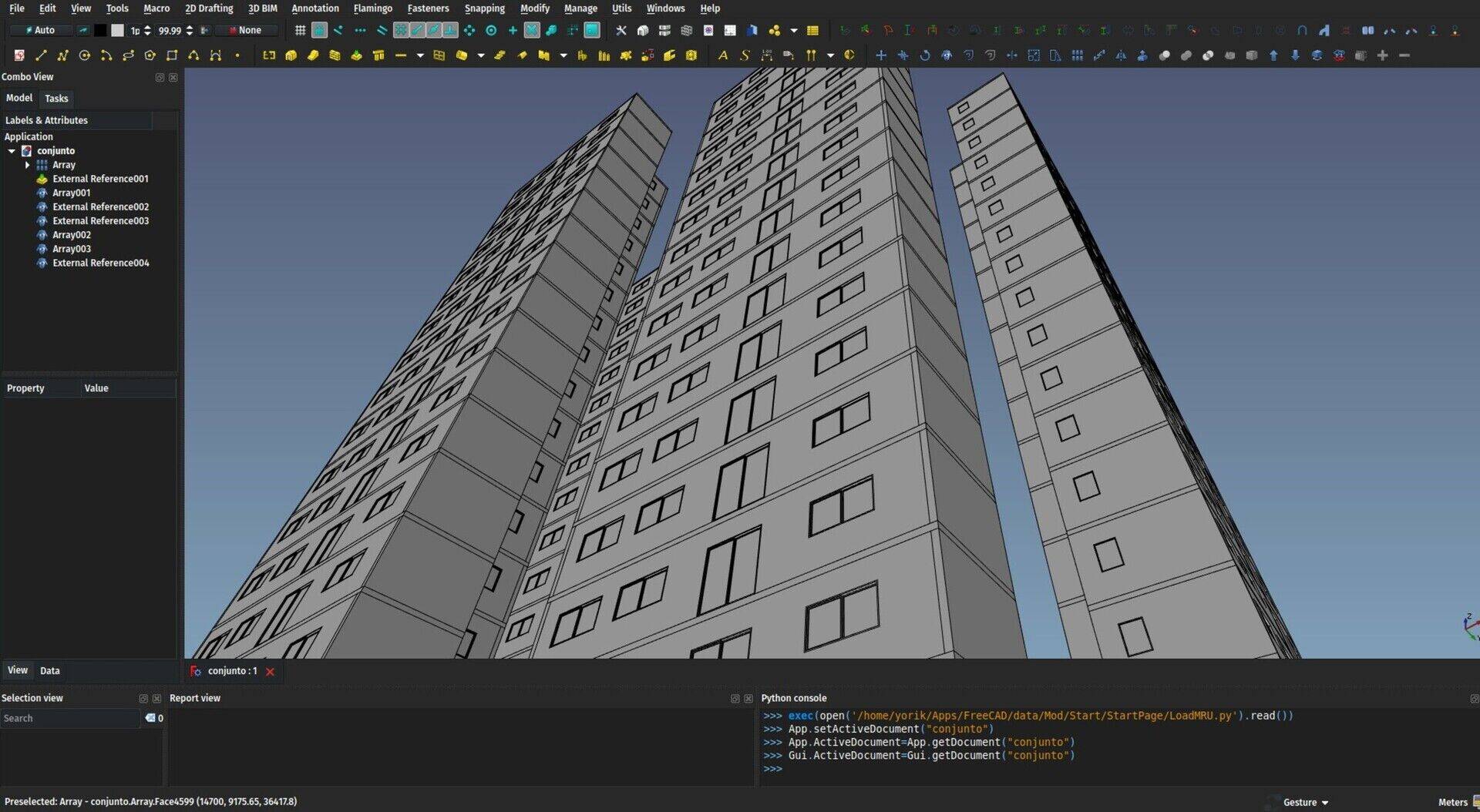
When you create a reference object, you give it a path to another FreeCAD file, then you can choose one of the included shape-based objects inside the file. The implementation is very simple: The Reference object doesn't open the included file. It just unzips the stored brep data of the object you specified. Any object with a shapecan be included, including, and that's the interesting point, BuildingParts. As I explained last month, internally, the BuildingPart always keeps a shape that is a compound of all the shapes of its children. Compound shapes in FreeCAD are very cheap and fast to produce (no boolean operation involved). So you can group anything you want, a whole storey, a whole building, etc... inside a BuildingPart, then include that BuildingPart as one single object inside another model.
The referenced object is a fully valid shape object, that you can move, rotate, duplicate, clone, project in 2D, and snap to it like any other. At the moment, it will be exported to IFC as one monolithic IfcBuildingElementProxy object, that's something to work further on in the future.
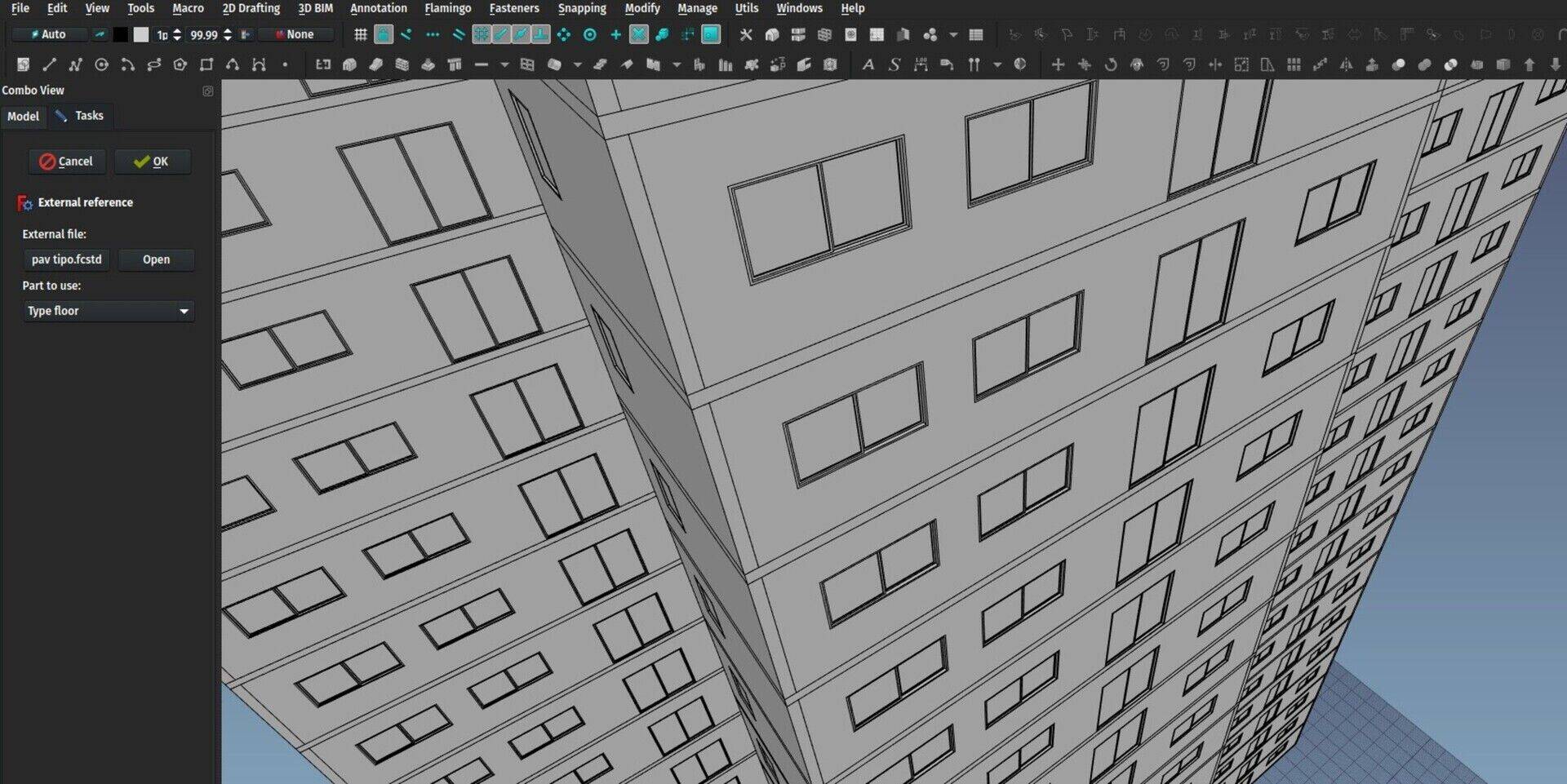
If you follow FreeCAD's latest developments, you might be asking yourself why this was not based on Realthunder's Assembly3 branch, which provides about the same functionality? There are a couple of reasons to that, basically because I wanted to try a very simple implementation, while his is rather complex, and also the aim is different: The Assemby3 functionality aims at pretty complex models, with not so much geometry, but with complex hierarchies and relationships. In BIM, we are aiming at very large models with very little or no relationships at all between the included parts. In any case it can certainly be interesting to have both approaches in FreeCAD.
Further immediate development will be the retrieval of colors. At the moment only the shape of included objects is gathered by the reference tool, we need to make the BuildingPart store not only the shapes of its children, but also the face colors, like the Part Compound does. Then we can read that as well when we include an object from another file.
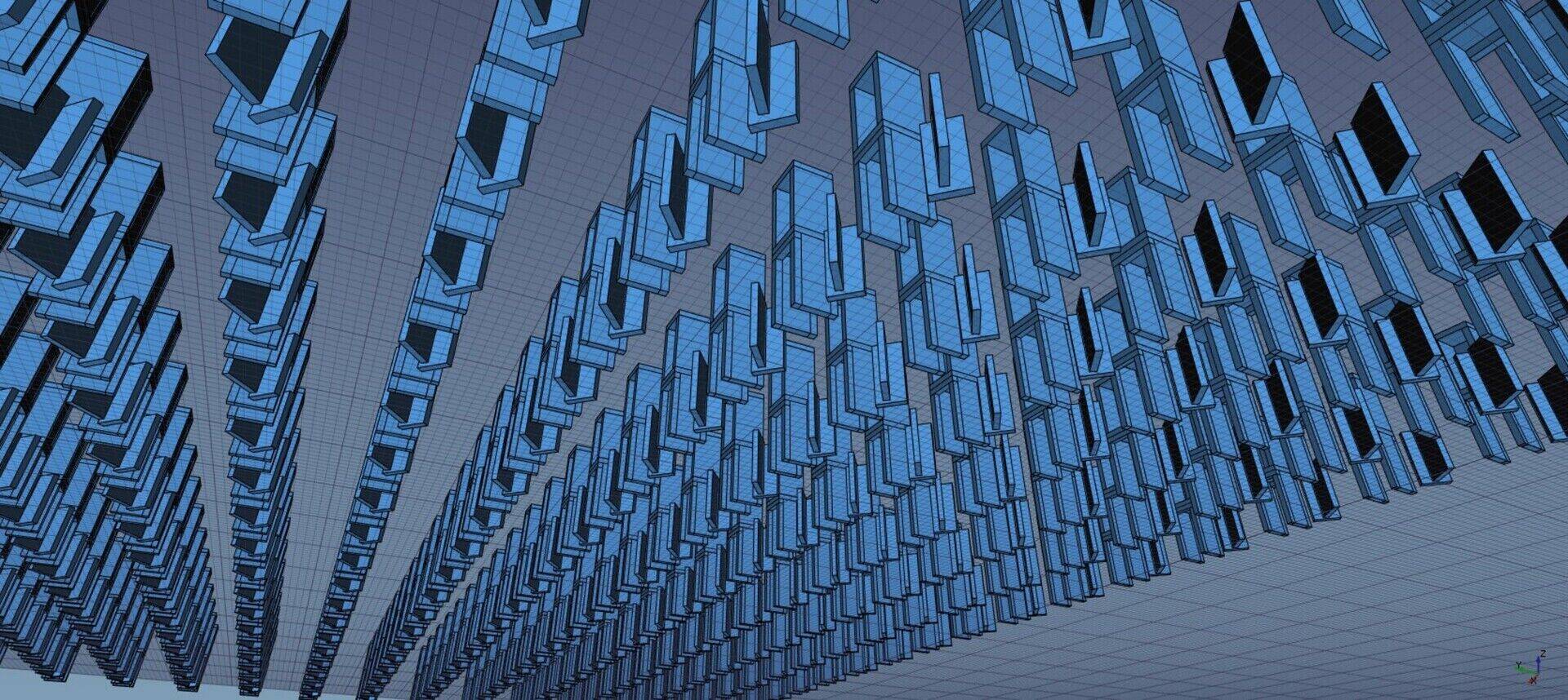
Next, I'll also add an option to have the BuildingPart also store an OpenInventor representation. This will allow us to load only that representation from the included file, not the shape itself. This "lightweight include" would give blind-fast imports, and would have virtually no limit in terms of model complexity. There are a couple of caveats to solve, that I already experimented with the "Hi-Res" mode of Arch objects (snapping and selecting and everything else based on element names doesn't work correctly), which is something realthunder has been able to solve much better in his branch, but there is no reason to not be able to make it work.
FreeCAD for Inventors book

Finally, Sliptonic, a long time FreeCAD developer and main brain behind the Path workbench, has written a new FreeCAD e-book called FreeCAD for Inventors. It is available for purchase on Amazon and Kobo. It uses the same basic structure of the FreeCAD manual, that is, a general walk through the different parts and workbenches of FreeCAD, with a series of pretty interesting exercises. Sliptonic has also paid close attention to the usual requests and difficulties reported by newcomers to FreeCAD, and tries to address them in the book. Definitely a very good entry path into FreeCAD, if you are new to it.
That's it for this month, next month I'll attend the Google Summer of Code Mentors summit in San Francisco (and spend a couple of days in Mexico City on the way back). I'll be sure to dutifully report here.
Cheers!
Yorik
Urban sketching in Salvador
The drawings I did during the wonderful national encounter of urban sketchers in Salvador da Bahia, Brazil


há algum tempo percebi que a ferramenta "cut with plane" não está funcionando na versão para windows (64b), nem a versão estável e nem a 0.18x (que é a que eu tenho usado...) acho ela muito importante para corte de paredes especialmente sob telhados. Que tal, assim que for possível, você dar uma verificada? Obrigado pela atenção e pelo excelente trabalho em um software incrível.
sergio
These guidelines are more human-oriented than others that currently used in FreeCAD. It is very easy to get lost in the very Complex and Powerful application such as FreeCAD.

One question: Why are you using QCAD rather than LibreCAD?
FreeCAD BIM development news - August 2018
Hi there,
One month passes bloody fast, doesn't it? So here we are again, for one more report about what I've been coding this month in FreeCAD. Looking at the text below (I'm writing this intro after I wrote the contents) I think we actually have an interesting set of new features.
None of this open-source BIM journey would be possible without the help of everybody who contributes to my Patreon or Liberapay campaigns, and therefore allow me to spend a good amount of working hours per month on FreeCAD. Thanks a million to all of you, it is really making a difference for FreeCAD, we're well on our way to a good, open-source BIM application.
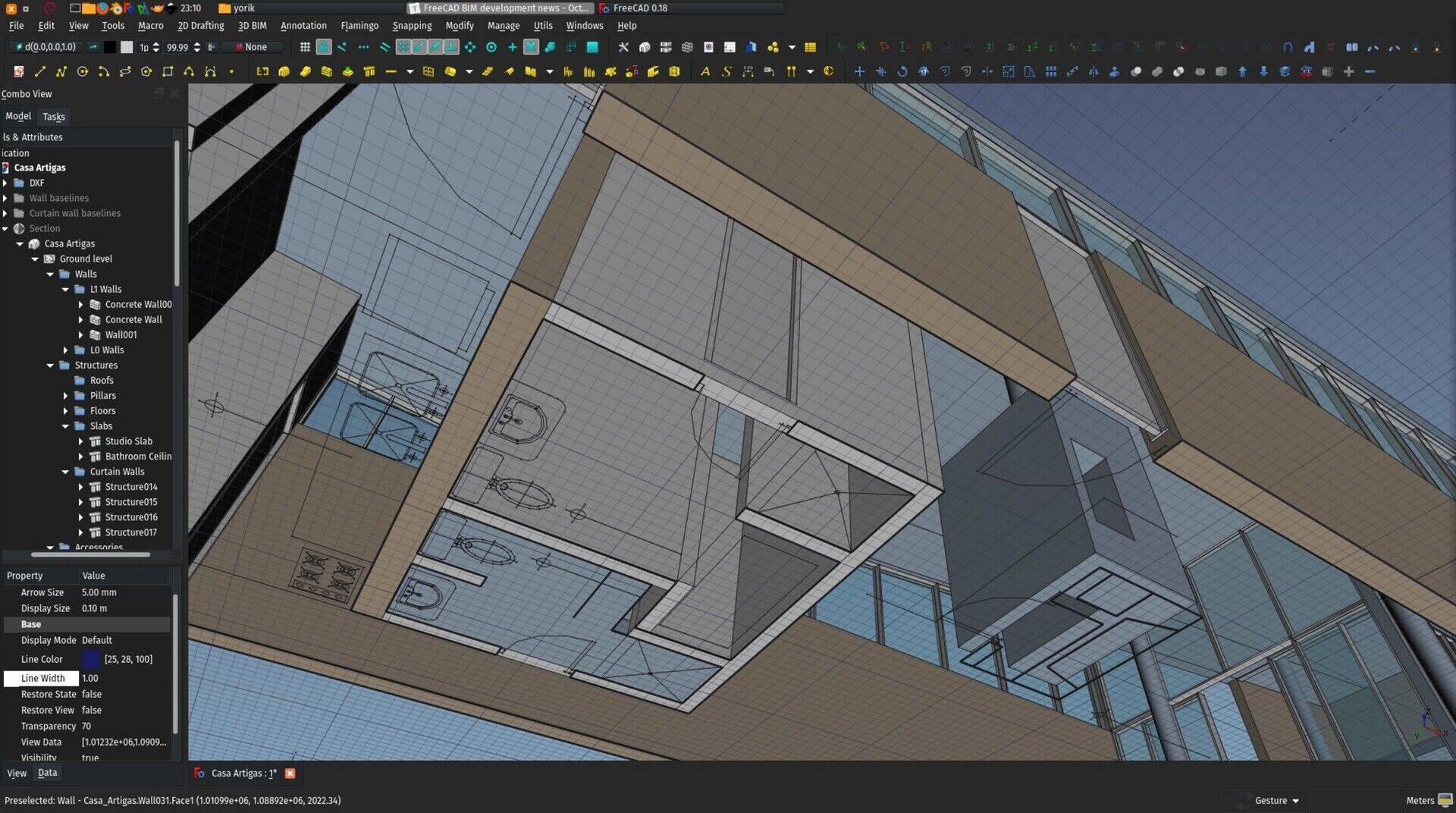
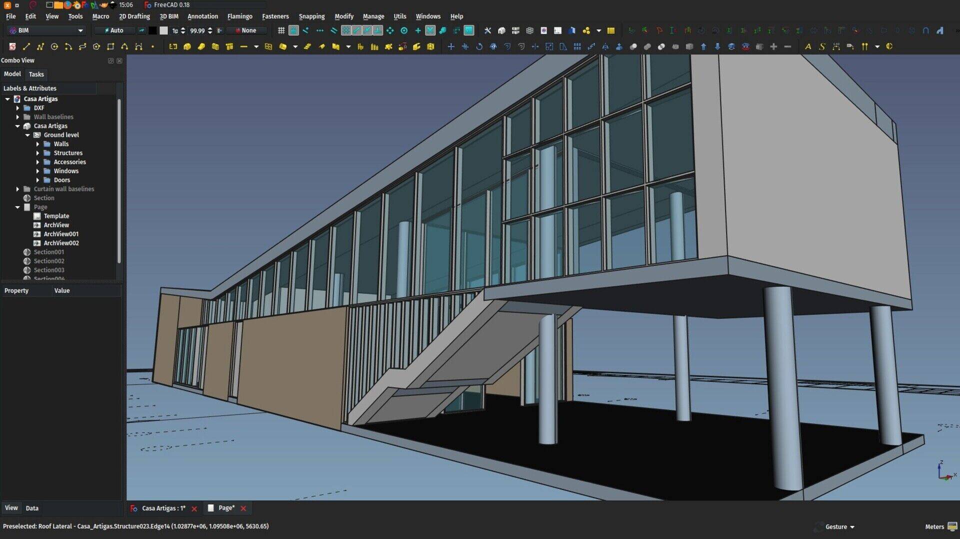
The house illustrated in this post is a famous house built by architect Vilanova Artigas in São Paulo and was modelled by Wilson Melo.
So let's have a look at this month's features, but first, here goes our monthly video:
The video: 2D drawing
In FreeCAD, like in most other BIM applications, many 3D objects are based on 2D objects: Walls are based on a line, columns and beams on a 2D profile, etc. In most cases, you are not forced to draw that 2D object yourself: You can draw a wall directly in the 3D view, or you can place a structural component by selecting a preset profile from a list. However, all these objects can also be made from a custom 2D object that you draw yourself. There are many ways to do that in FreeCAD, this video will give you a quick overview of the available options.
Ideastorming
As announced last month, we are reaching the first goal I have defined on Patreon, which is, a place where we can discuss BIM ideas and features to be implemented in FreeCAD, and you guys can vote for them, and I would do my best to implement the most voted ones. I had a look at the different (open-source and not) solutions available to do that efficiently, but unfortunately the results of this search are not very good. Most "feature voting" applications are very old and unmaintained, or require a heavy web infrastructure to be put in place, and you will certainly agree that our time should be spent better than in maintaining heavy web infrastructures just for that purpose...
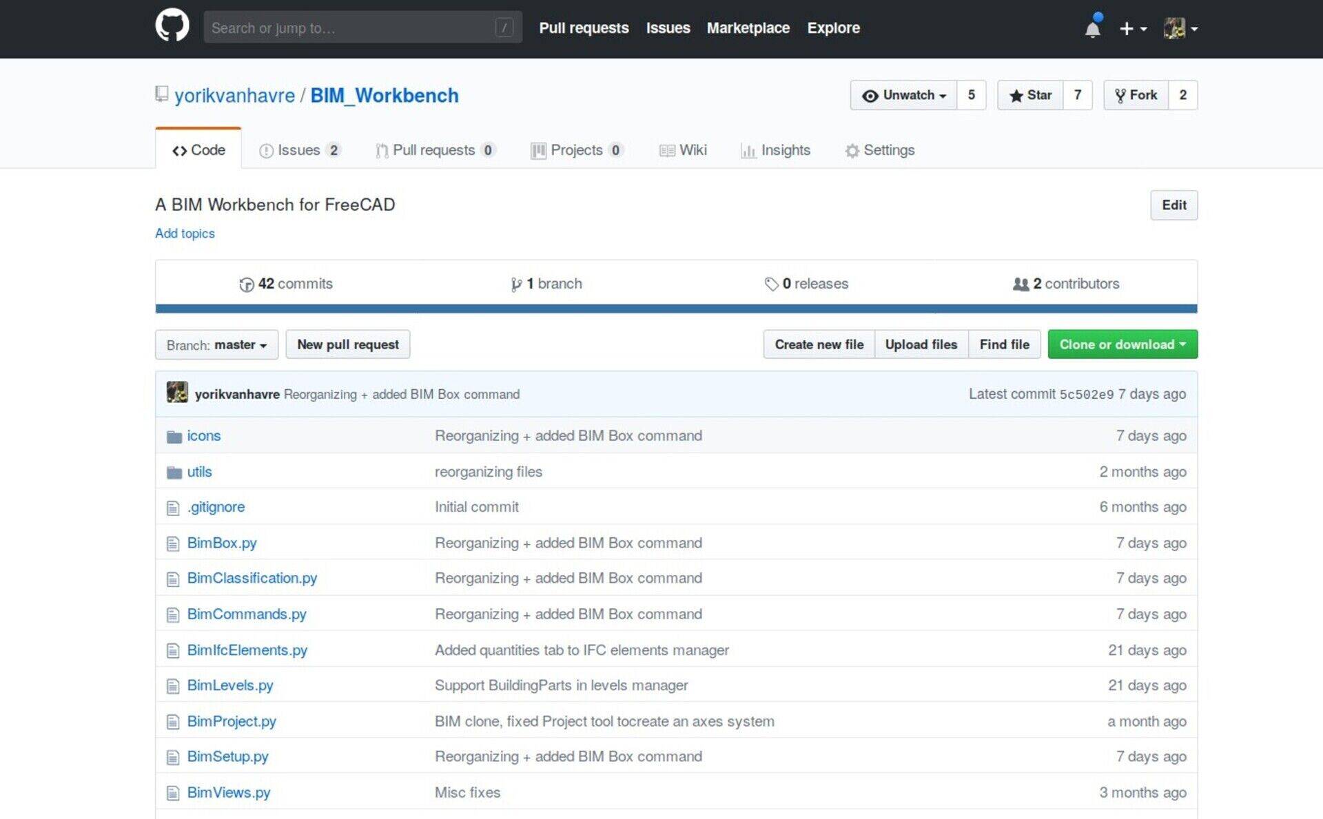
So I thought, why not simply use the Github issues system? It is possible to vote there, submit new ideas, etc. Most open-source projects hosted on Github use it. It might not be the ideal (given the fact that Github is now owned by Microsoft, etc..) but at least it's easy to use, anybody can add new ideas, vote for existing issues (give it a "thumbs up" , etc.
I am starting to put some ideas on the BIM workbench Github page, have a look there under the "issues" tab, I'll add more in the coming weeks. Don't hesitate to add your own ideas there, or comment as much as you like on the existing ones.
Full groups hierarchy in IFC
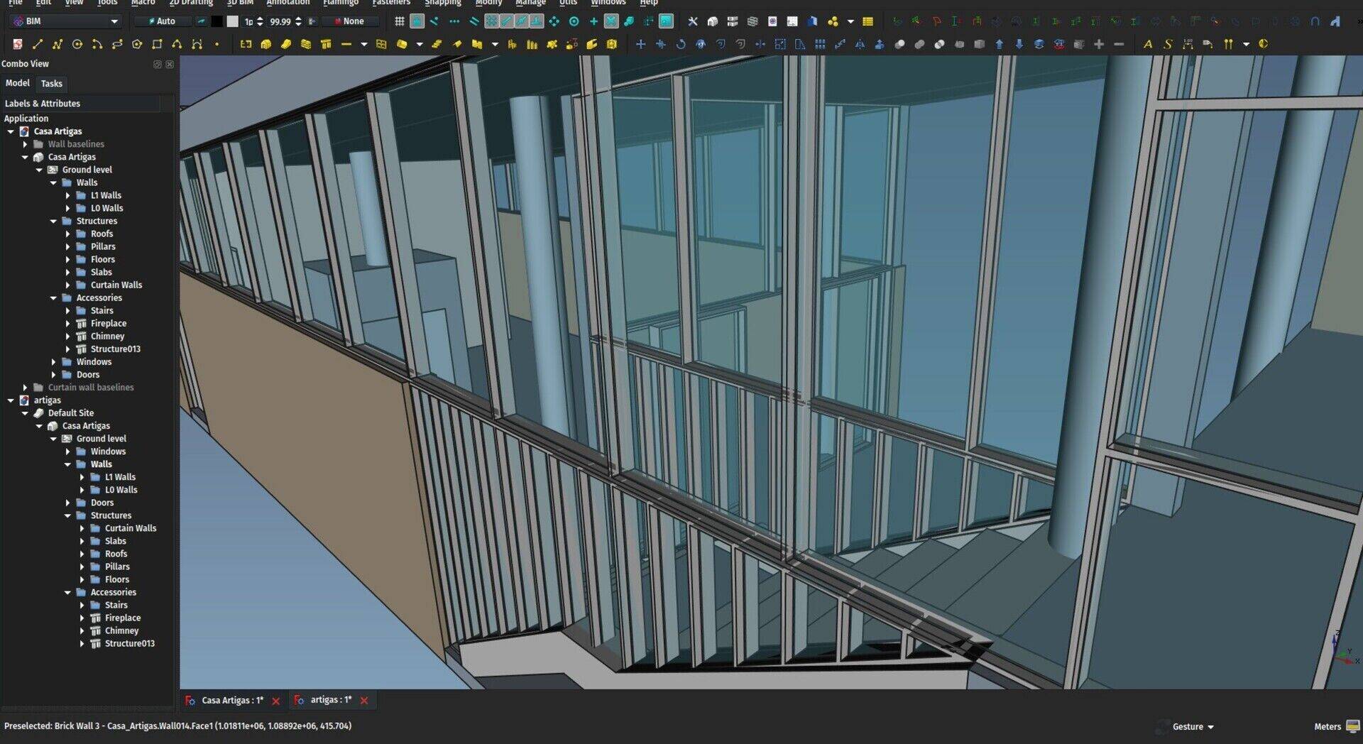
I discovered a small but bright IFC trick recently that might not be "proper" IFC behaviour, but that is definitely improving our FreeCAD workflow a lot: Groups, in IFC, are handled by an object called IfcGroup. However, groups are not really part of the standard way to use IFC, which is to use spatial structures (Buildings, Storeys, Spaces, etc..). As far as I could see, they are just offered as an additional way to create relationships between objects, if anyone really wants to. You will rarely see an IFC file that contains groups. Revit and ArchiCAD, although both offer the functionality, don't use groups much.
In FreeCAD, however, groups are a very important feature. All the objects of your model are appearing in the tree view, so it is very important to organize them. Grouping is an extremely powerful way to organize your model, and, unlike other methods such as using storeys or layers, it is completely free from any "meaning". You, the user, decide how you want to organize your model. Will you group all your walls under a "Walls" group? will you make sub-groups for different types of walls? Will you not use the materials system at all, and instead group all your objects by material? The model is yours, the choice is yours. Also, every project is different, it makes little sense to force users into one kind of arrangement. An office tower model should definitely not be organized the same way as a house.
In FreeCAD, you can mix everything together: Have groups inside levels (which are now handled by the BuildingPart object), levels inside groups, groups of buildings, anything your wild imagination (or very concrete requirements) dictates. But this was all lost when exporting to IFC.
Now I discovered that IfcGroups are actually derived from the same base entity as other IFC grouping features such as Storeys or Buildings, and, as such, they share some functionality. More important, it is possible to stack groups as part of these other entity types.
So from now on, you can export your wild model structure to IFC, re-import it, it will come back exactly as it was. Most of our BIM competing applications might still not be able to cope with such a complex model structure, poor them, but hopefully they will do their homework at some point.
Forgive me for the quite exaggerated last sentence, but I couldn't resist 
IfcElementAssembly support
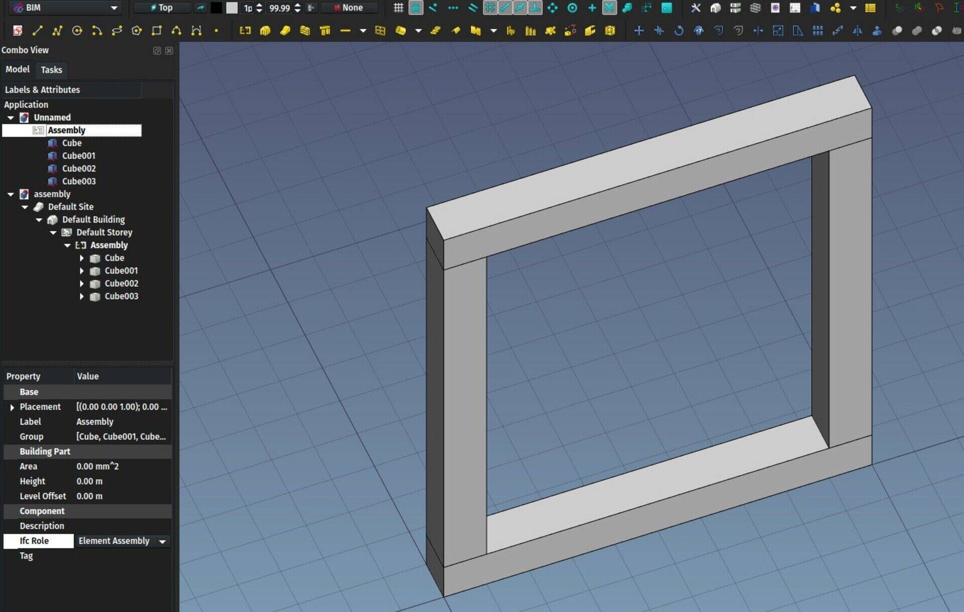
Another IFC feature I've implemented in the last month, is support for IfcElementAssembly, which is the standard IFC way to define an element made of several other building elements. For example a truss system, or a bathroom unit. It is a bit like grouping, with the difference that the assembly is not just a group but a real, physical, manipulable object.
In FreeCAD, any BIM object can be an assembly of any kind of geometry or other BIM objects. You just need to add them to its "Additions" property. However, until now, if the host object was a wall, it will be exported as a wall.
Now, if you change the Ifc Role of any BIM object to Element Assembly, it will be exported as such. But even better, BuildingParts will also be exported as IfcElementAssembly when its Ifc Role is set as such. And it is much easier to add objects to a BuildingPart, as you can drag/drop objects into it in the tree view, and is a much more "intuitive" way to construct an assembly.
When importing an IFC file containing IfcElementAssembly entities, they will be rendered as a BuildingPart, so all their components will be available and manipulable.
On our way to a full roundtrippable IFC <-> FreeCAD workflow!
Quantities
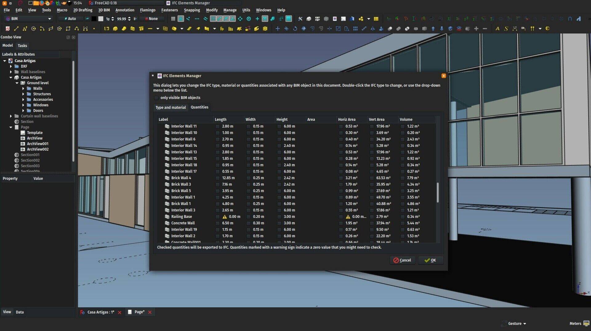
Finally we now have preliminary support for quantities. I say preliminary, although it works well already, because I'm still not sure about the future direction of this.
Basically, the IFC format supports defining objects by quantities. Together with the geometry of an object, for example a wall, you can also attach quantities to it, for example a height value of 3 meters, or a thickness value of 20 cm. This is all arbitrary, you can decide yourself what name you will give to these quantities (it it "thickness" or "width"? "largeur" maybe? or "??"?) and, even more problematic, you can make them lie (the "thickness" value you give is not the same thickness as the geometry you provide).
So it is complicated to trust these values. However, the point is not there. The idea is that an application that doesn't have geometry support, for example a spreadsheet application, would be able to open an IFC file and build a list of quantities of all the elements in the file, without the need to have very complex geometry tools to extract that information from the geometry.
The idea is brilliant of course. Imagine "opening" your IFC model in Excel?
So here is how it works in FreeCAD now. The IFC Elements Manager (sorry, the documentation is not there yet at the time of writing, will work on it in the coming days) of the BIM workbench now has gained a new tab that shows available quantities for BIM objects. So far, I only considered objects that had standard, universally recognizable quantities such as width or length. This will be developed further along the way.
For any of them, you can now mark if you want those quantities to be exported to IFC. That screen will also show a warning sign when such a value is zero, which probably indicate a problem somewhere that you should look at before exporting.
These quantities are then exported to IFC and attached to the corresponding object. When reading back an IFC file, the quantities are not read, as we prefer to get them from the geometry, which is more trustworthy. In the future, we could think of comparing what the geometry says with the given quantities (FreeCAD as a lie detector for IFC files?), but I can't think of much use for that.
Start center redesign
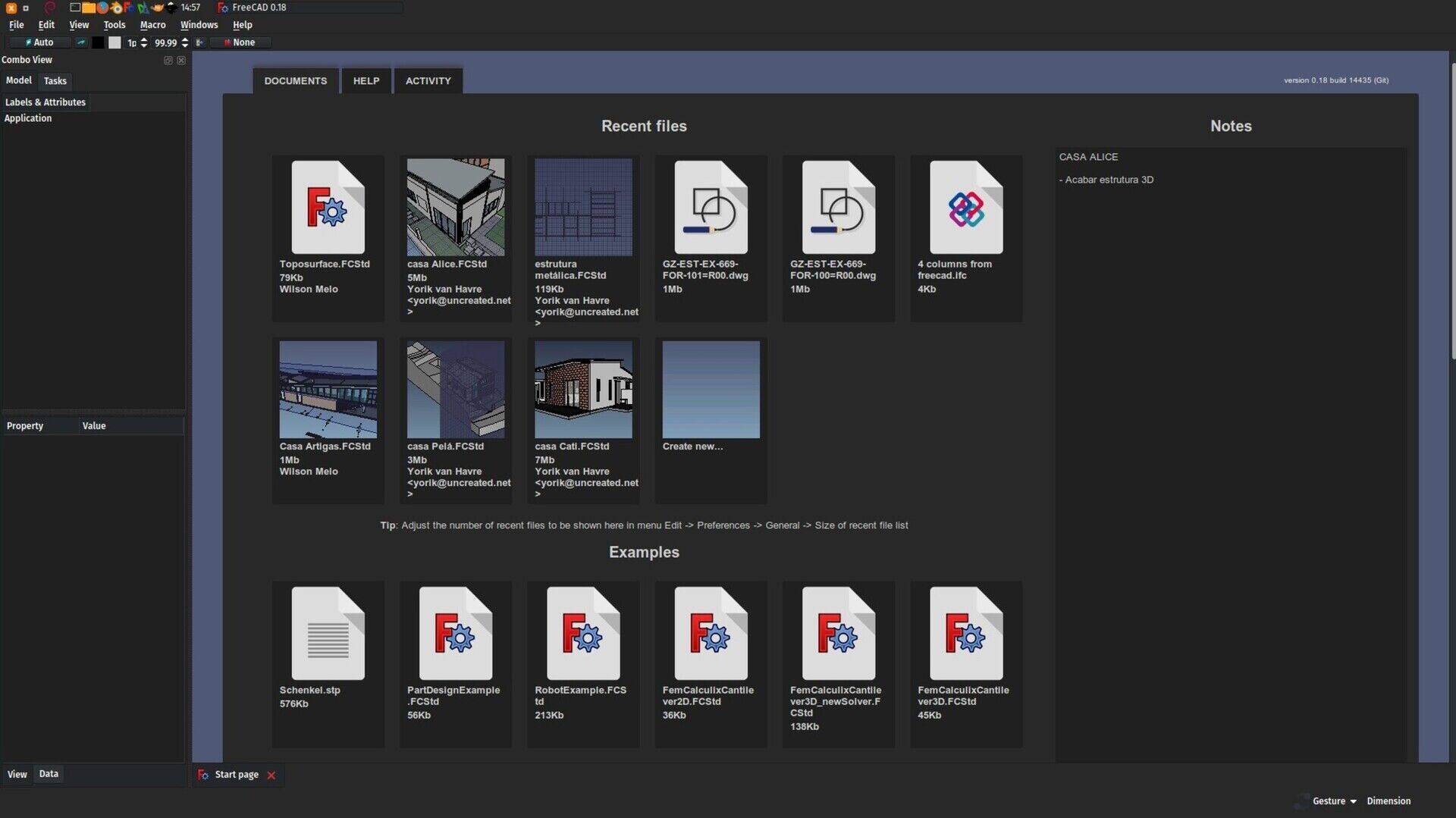
I had been busy with this for some time, and it's finally ready. The old start page, which appeared when you opened FreeCAD, was something a bit clumsy and not very usable nor interesting. Now we have something that is much more useful, both for newcomers and experienced users. There are three tabs, one for your files, one for documentation, and one to have a quick peek at the recent activity in the FreeCAD world (latest changes to the source code and latest posts on the forum), which is a feature many users liked in the previous version.
All of this is customizable, translatable and themable, and you can even replace the start page by any HTML file of your own. That can be useful for example in companies or schools so they can display additional content.
There is also a "notes" area, that you can enable in the Start preferences, where you can write text that is saved across FreeCAD sessions. This could be useful as a kind of "FreeCAD to-do list".
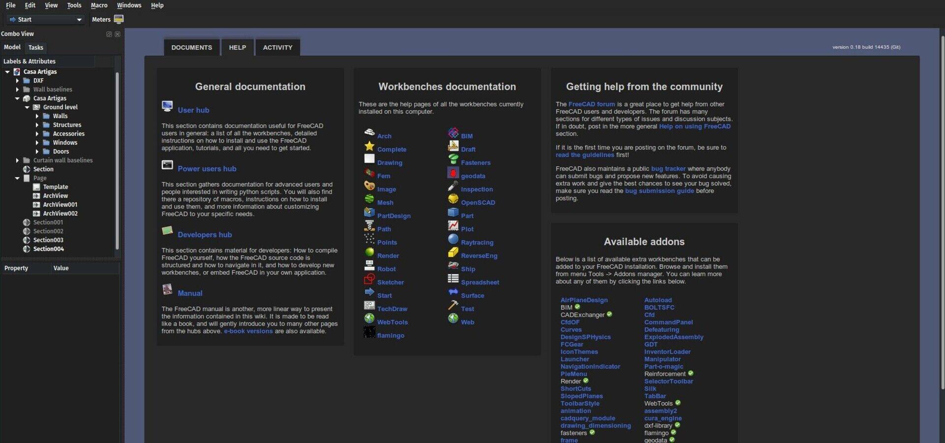
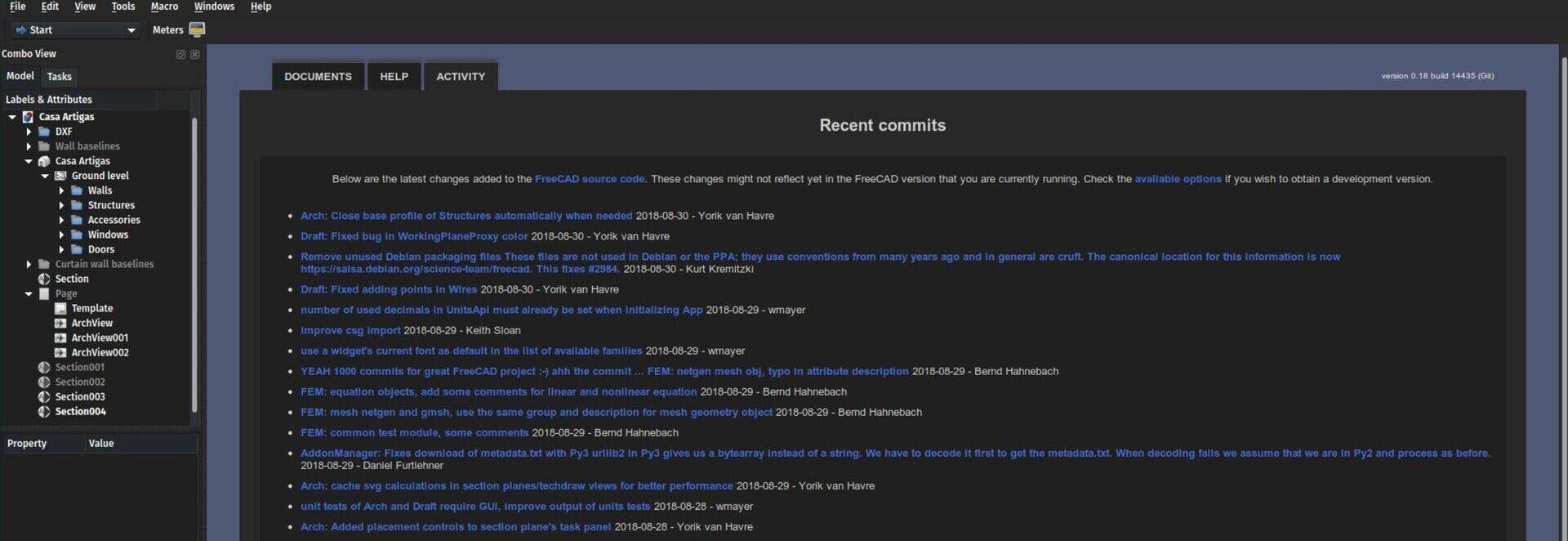
There are still some small hiccups depending on the platform, but we'll address them on the way. Don't be scared about the colors in the images above, I adapted the start page colors to my desktop theme (you can do that in Edit->Preferences->Start), but by default it looks like this:
New website
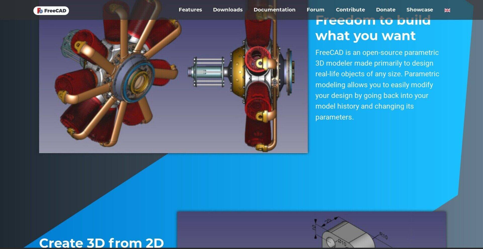
This was not done by me but by FreeCAD user AR795, with the help of many others, bu have you seen the gorgeous new FreeCAD website? Next we'll adapt the rest of the FreeCAD web universe (wiki, etc..) to the same aspect.
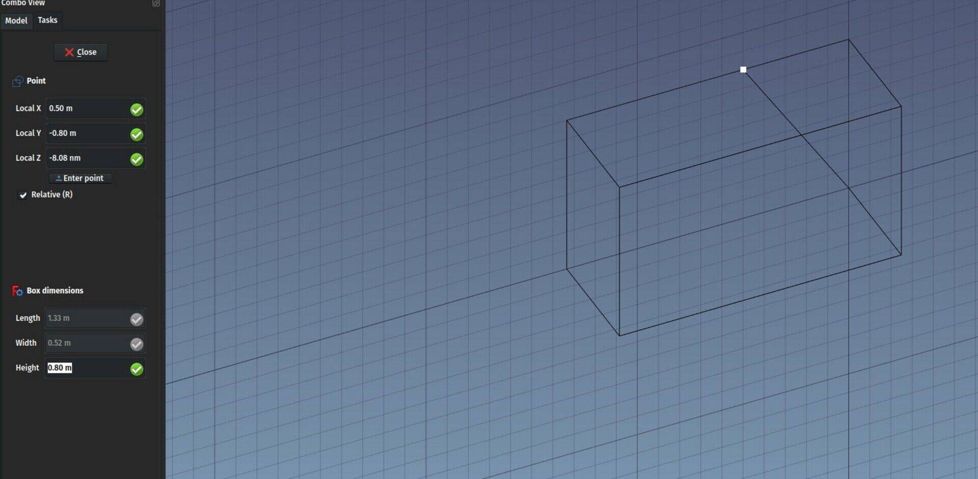
BIM Box tool
Until now, the BIM workbench featured, among its 3D tools, the standard Part Box tool. Using boxes is very practical in BIM, more than half of the geometry we create is usually made of these rectangular shapes, and the Part Box is a very simple and versatile tool that has 101 utilities. The way it is created, however, is often annoying: A 10mm x 10mm x 10mm box appears at the origin point when pressing the button, which requires several additional operations to move it to the correct location and set its length, width and height dimensions. Most of the time I was using a Draft Rectangle that I then extruded, which was faster.
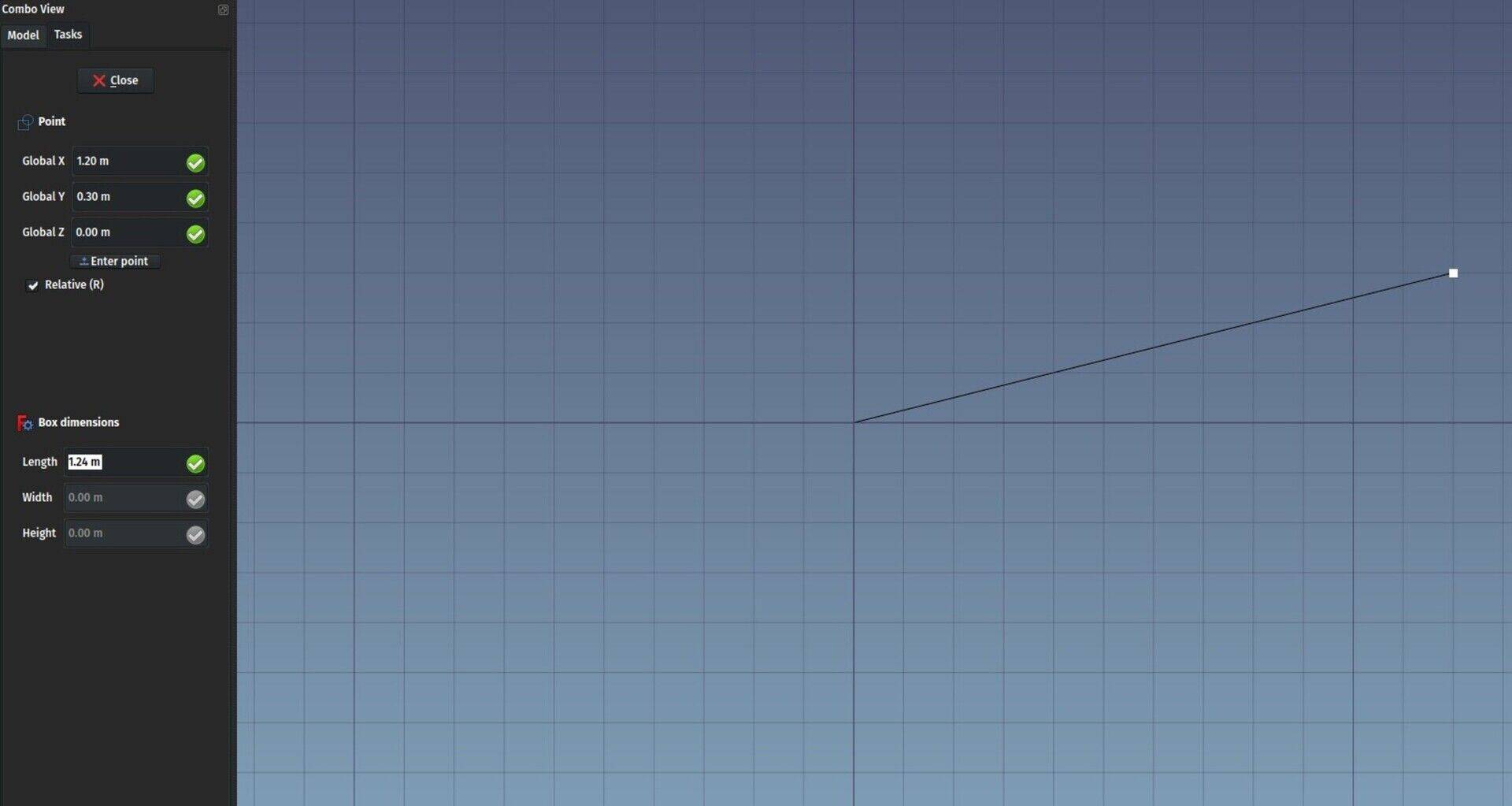
Now I rescued an existing macro and turned it into a full new BIM Box command (sorry, no doc yet) command, that still creates a Part Box, but graphically in the 3D view. You give two points to define the base line (length), a third point to define the width, and a fourth to define the height. You can also enter length, width and height manually in the Task panel, but you still need to click the two first points to define the position and orientation of your box.
These boxes can be used as walls (just press the wall button with one selected), beams, columns or any other BIM object, or as a subtraction to any of them (select the box, CTRL+ select the host object, press the Remove button).
Section plane controls
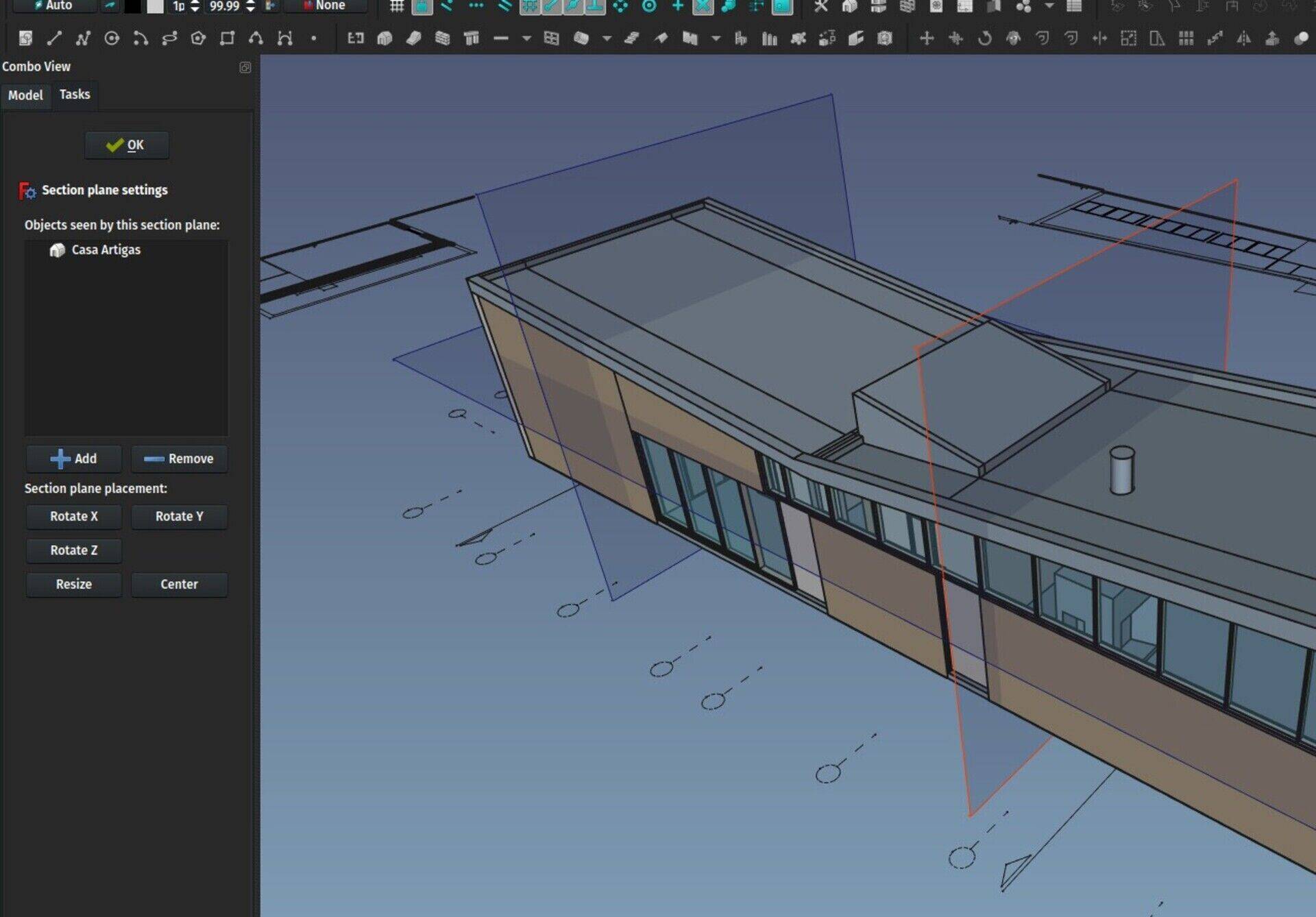
The Section Plane tool has also gained a series of improvements. First, when you create one, if you have objects selected, for example a building, the section plane will automatically be placed at the center point of the building and resized to encompass it.
Then, by double-clicking the section plane to enter its edit mode, you now have several controls to flip it in other directions and resize it to fit. So it is now much easier and faster to create multiple views and sections.
Section plane caching
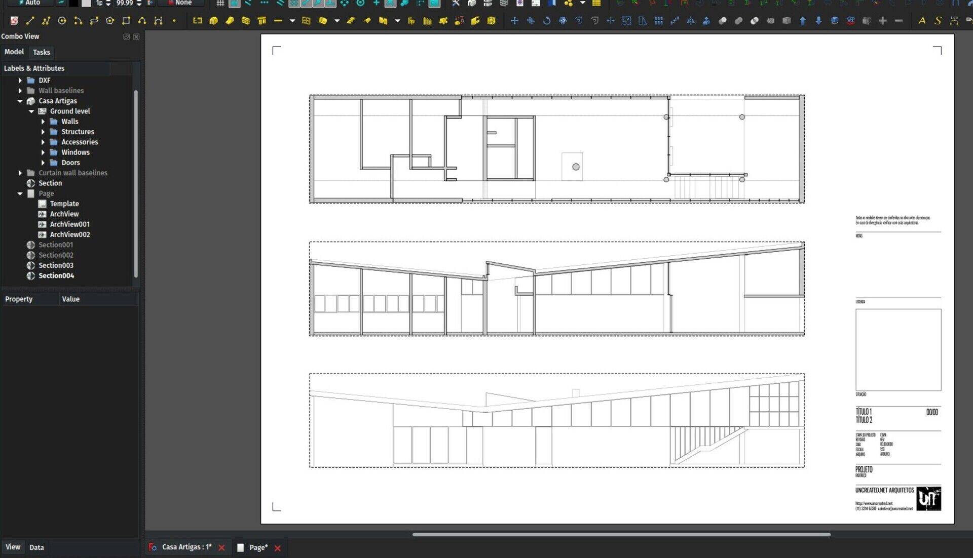
With Wandererfan, we are working on having proper support for Section Planes in TechDraw, which is the FreeCAD workbench used to produce ready-to-print sheets. At the moment, you must still use the TechDraw ArchView tool, which is the only one that supports Section Planes. However, that tool has many limitations, because it produces its view through SVG, and therefore looses many of the TechDraw features such as the ability to add hatches and dimensions.
But while proper support is not ready, I already experimented with caching. The contents of the TechDraw ArchView is now cached, and only recalculated if the objects seen by the section plane change. So you can now move, rescale, change thicknesses, etc... of ArchViews without redoing the heavyweight calculations, which makes it much faster.
This seems to work pretty well, so that might be a good idea to implement further in TechDraw later on.
Terrain macro

Finally, I built this little macro the other day that builds a whole Site object out of a series of contour lines, that you can for example import from a DXF file. Your contour lines can be organized in any way you want, grouped in different layers, and don't need to be connected into wires (they can be a series of simple lines). The macro solves it all.
Internally, it breaks everything into separate edges, re-joins everything into wires, turns the wires into b-splines, sorts them by elevation, then builds ruled surfaces between the contours, then builds a shell object out of the surfaces. Finally, that shell is used as the Terrain property of a site.
There will be many situations where it won't work correctly (for example the sorting by elevation will produce wrong results if there is more than one contour with a certain elevation), which we can adjust later on, until it is good enough to become a real FreeCAD tool.
But the results are quite good already, and of a much better quality than the point cloud-based method I used some time ago. Plus, it is easily editable by editing the b-splines.
That's it for this month, see you in September!
These are actually two different projects, born more or less at the same time, that some fatality made choose the same name... We had some contact with Mr. Koh already in the past, but the two projects are really very different and there was not much of a "common ground" where some sort of collaboration could take place... The only annoyance is sometimes we have to explain this "two different projects" thing (sometimes it is more embarrassing, some very serious websites did quite poor copy/paste journalism and got awfully confused between the two), but I guess otherwise it is not a problem for any of us, and all users of respective apps are used to the name, so it basically stayed that way until today...
I am very interested in BIM and freecad. It looks like for my future home that is the way to go.
"The discovery of structural form" by Kemp & Tenenbaum (2008), discusses their approach to support structure learning methods that closer to human abilities.
So yeah... I need to have a better look at it.
FreeCAD BIM development news - July 2018
Hi folks,
This is the monthly development post about the development of BIM functionalities of FreeCAD. This month we won't have a video here, because there is quite a lot of stuff to show already, but next month I'll resume making videos, and I'll try to begin to show real projects in them too (not sure how doable that is, as it might easily make videos pretty long, but we'll try).
As usual, thanks a million to everybody who makes all this journey possible by supporting me on Patreon or Liberapay. As you might have heard if you are using Liberapay, they currently have problems with their payment provider, and operations are suspended there at the moment. Many of you who are using Liberapay opted to empty their online wallet by distributing their remaining money between the projects you sponsor, so I got quite an unusual amount of money this month (around 700 EUR). I am keeping this money intact for now, maybe there would be something cool to do with it, I don't know yet.
As I wrote here last month, by combining what I earn on Patreon (about 700 USD/month) and Liberapay (around 90 USD/month), we are hitting the first goal I had set on Patreon (750 USD), which is to set a site, or forum, where you guys can propose and vote for ideas to be implemented and I would try my best to make them come true. I lacked time to organise this, so it will be for next month. But it's definitely coming!
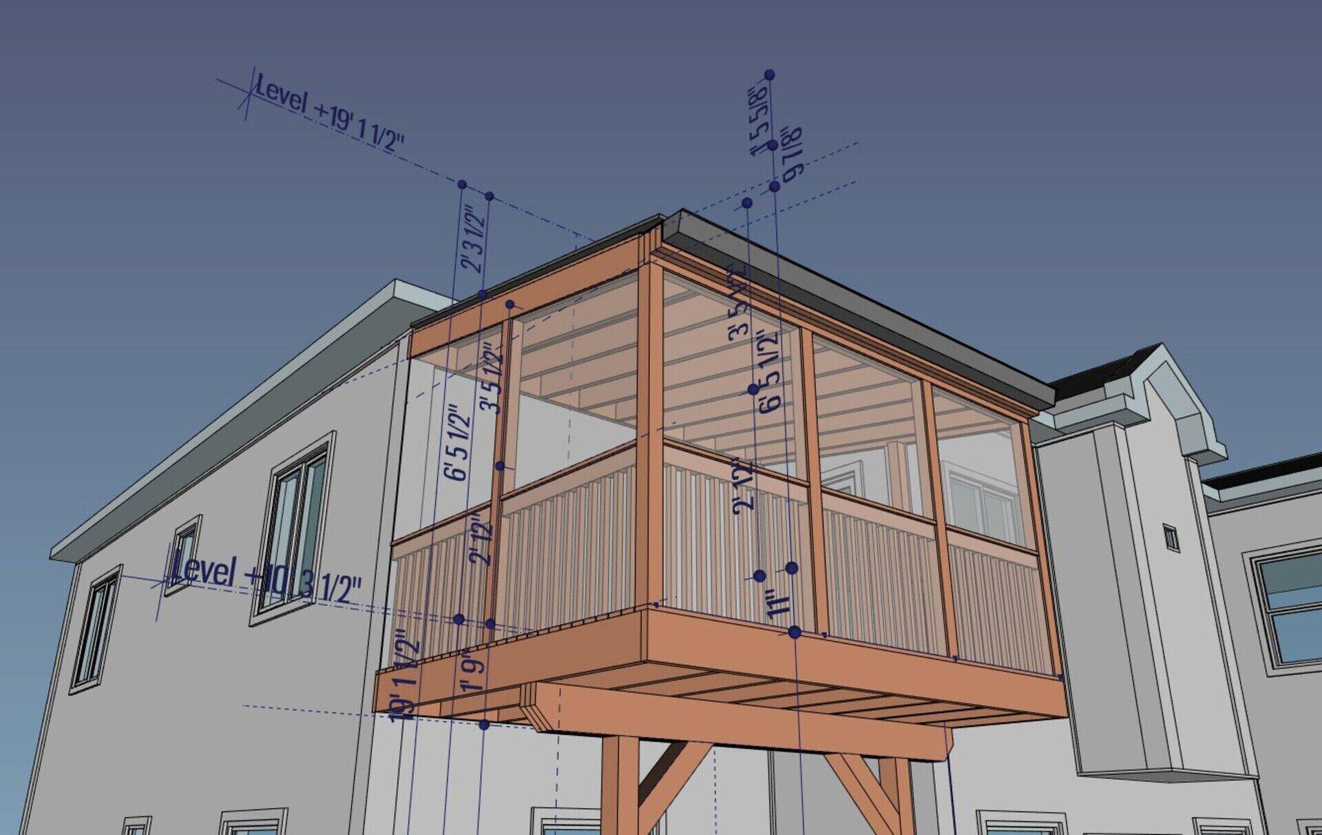
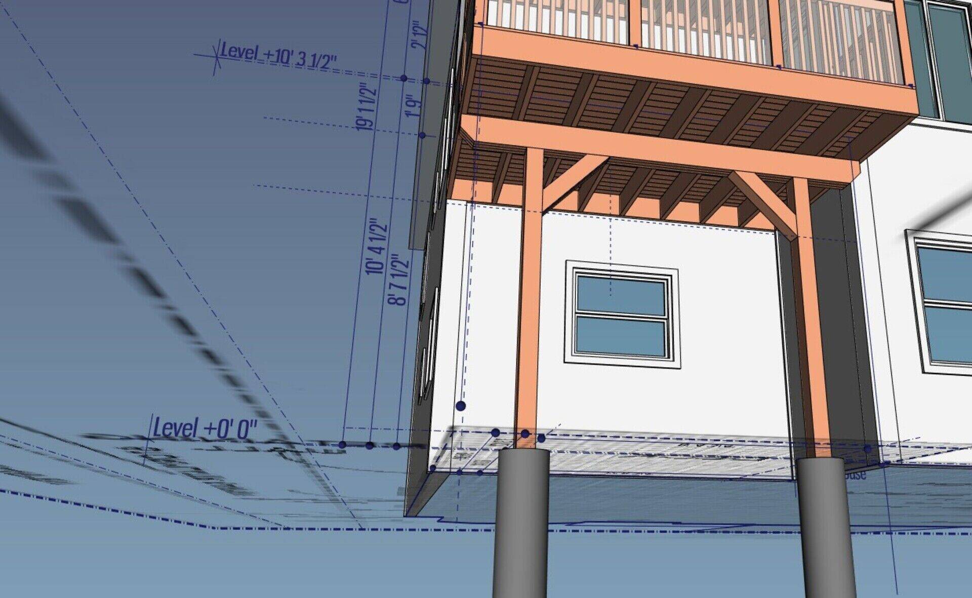
The project illustrated in this post is by OpeningDesign
So on with the stuff I did this month. Basically not much fancy graphical stuff, bu heavy work on the IFC side of things:
Property Sets and BuildingParts fully implemented and supported in IFC import/export
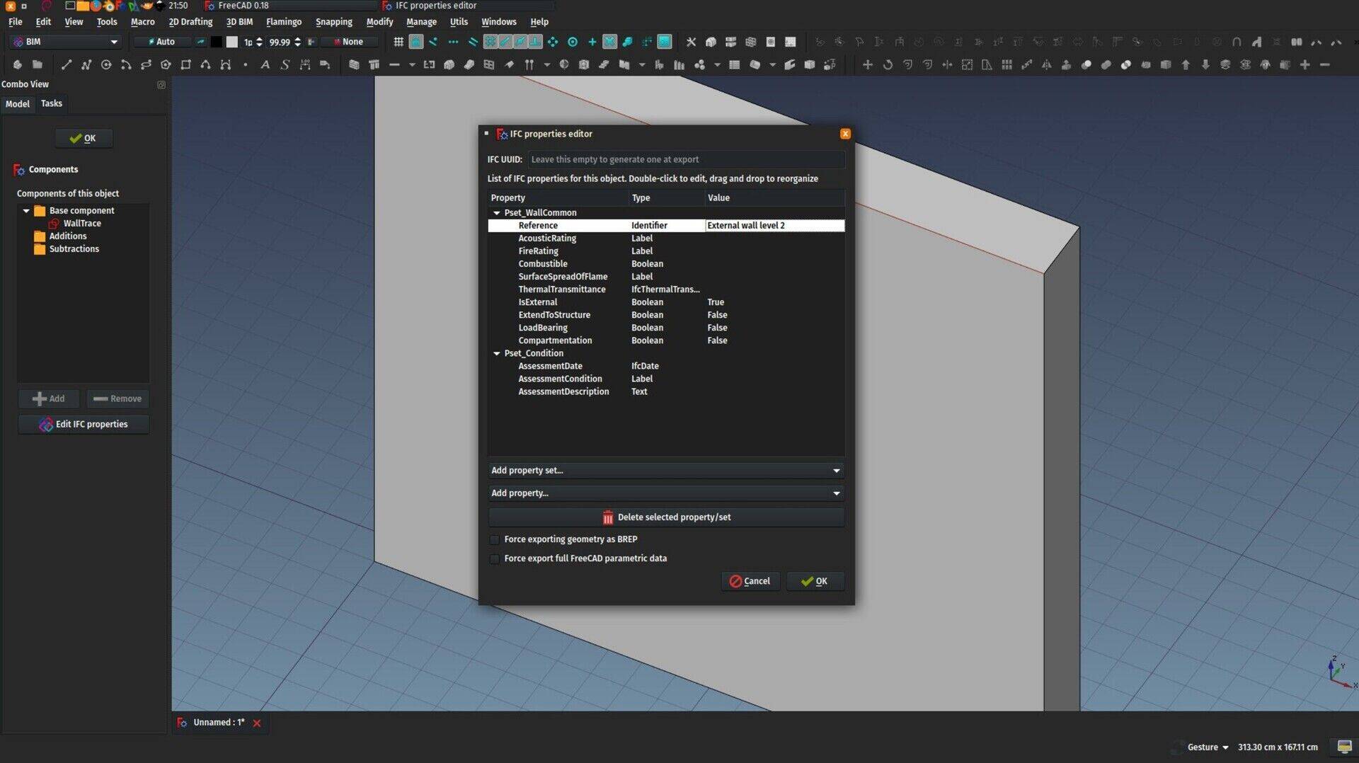
Last month I starrted with this by implementing support for property sets in FreeCAD. Property sets are a feature of the IFC format, where properties of an objects can be grouped into sets. As you can add any number or type of custom properties to any IFC object, you can also group them into custom sets. But the IFC format also provides standard sets, for example walls have a Pset_Wall_Common property set, that contains usual wall properties such as "IsExternal" or "IsLoadBearing". IFC Property sets are now fully supported when importing an IFC file in FreeCAD, and when exporting a FreeCAD model to IFC.
The other big feature I had been working on last month, the new BuildingPart object, which is made to replace the current Building and Floor objects with something more robust and versatile, is now also supported by the IFC importer and exporter. Depending on the IFC role that you give to your BuildingPart object, being Building or Building Storey, it will behave that way in the IFC file.
IFC properties editor
As important as the support for it in IFC, is the ability to easily edit, add and remove properties to/from your BIM objects in FreeCAD. So in the BIM workbench, we now have a full property manager tool. That tool can be launched directly from the BIM Elements Manager in the "Manage" toolbar or menu of the BIM workbench, or directly from inside the Edit Mode panel of BIM/Arch objects. If the BIM workbench is not installed, that option is not available.
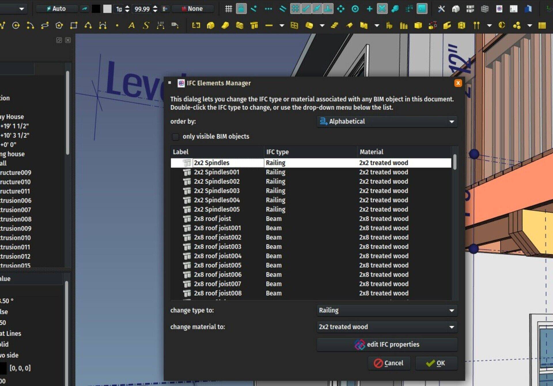
I'm not a big fan of that, "plugins" that spread out new functionality inside existing tools, I find that confusing and hard to discover, so the idea is not to go that way, and keep things clear between Arch and BIM workbenches and not begin to mix stuff between the two. But at the moment I'm still experimenting with all this, trying to find where it fits best, so consider these "intrusions" of the BIM workbench inside existing Arch tools just an experiment to see how it works best. If it consolidates into some "ground" functionality, it will go to Arch. If it's just an additional layer of UI work, it will stay in BIM.
The general idea is that you might want to use the Arch tools sporadically but you work mainly with other FreeCAD workbenches. Then you don't want to be bothered with BIM stuff. Or you are using FreeCAD mainly for BIM, then you want the full-fledged BIM workbench.
IfcGrid support
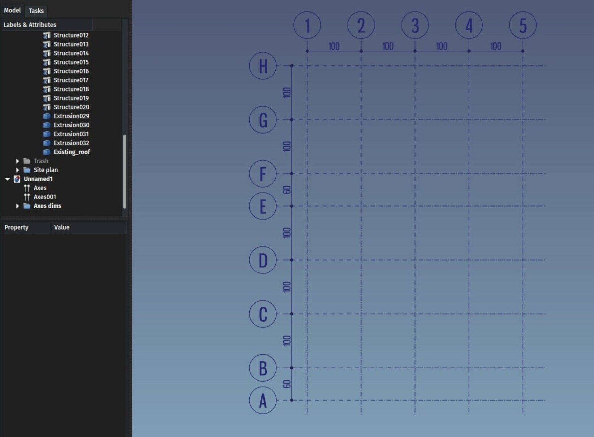
We already had several Axis tools in Arch/BIM, that can already cater reasonably well for your axes/alignment needs. However, they weren't very compatible with the way these work in IFC, where each axis is an independent object, grouped under an IfcGrid object that defines which ones are in the X, Y and Z directions. The IFC importer and exporters of FreeCAD now support all this transparently. In FreeCAD, axes can now be only one axis, so IFC grids can be imported as they are (several independent axes inside one grid/axes system), and on export, FreeCAD systems made of several axes will simply be decomposed into their individual axes.
IFC compression
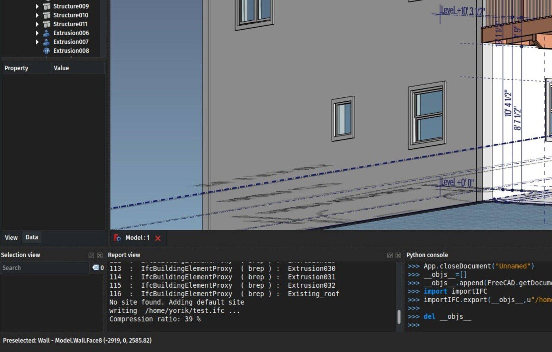
This is not a very good title for this feature, but it sounded powerful  Basically this is something that Revit does, that is fully supported by the IFC format. When you have two objects that share, for example, a same point (0,0,0) or a same colour, or a same property (Height = 3m), this information is stored only one in the IFC file, and used everywhere it is needed. This results in drastic file size reduction (30 or 40% everywhere I tested) because in IFC there are a LOT of those simple, basic pieces of information, but makes the file more annoying to read by human eyes, because if you are reading about an object at line 3500, you might need to scroll all the way up to line 15 to know the position of the object, and then half-way back at line 1500 to know its colour.
So this feature is now enabled by default, because in most cases you will want that compression, but can be unchecked in IFC preferences if you need a more human-readable file.
Not every IFC information can be compressed/reused that way at the moment, I just implemented some of the most common ones, but the list is easy to extend.
IFC shared profiles
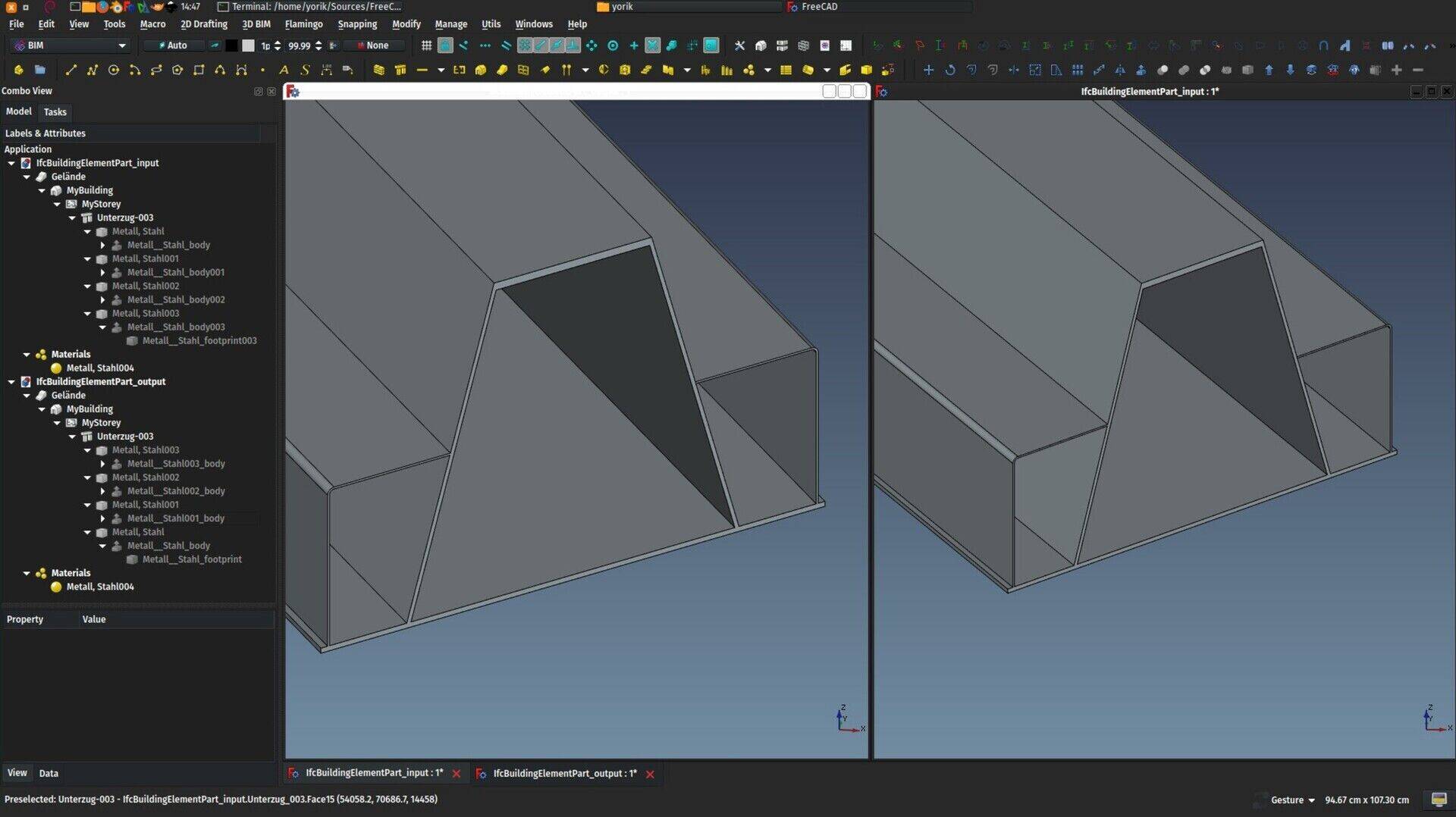
This is coming from an old dicussion we had with Ryan Schultz and Jon Mirtschin, about how to store and retrieve parametric profiles in IFC. The idea is that several objects can be based on a same profile, a very simple way to convey some "model intelligence" inside an IFC file. You modify the profile, all objects based on it change.
It turns out the IFC format supports that in a pretty simple way, very similar to the previous topic here above, you simply use the same IFC profile entity in different extruded objects. So the IFC importer now implements this, when different FreeCAD objects are extrusions of a same 2D object, it will be saved that way in IFC, and restored that way too when reading the file back.
So with all of the above we can now begin to get pretty accurate "roundtrips" when working with IFC files in FreeCAD. That is, the file contents you get when opening an IFC file you just exported are 100% identical with the original file.
Of course the concept of 100% equality is debatable, you WILL find something that is different from the original file, that is inevitable due to the complexity of the IFC format. But my idea is that we can settle on a general agreement over what reasonably needs to be there in order for us to consider it identical. I would say basically the model tree must be identical, the geometry of all objects must be identical, and all BIM-related properties of all objects must be there and contain identical values.
I think in many cases we have that now fully working in FreeCAD. I'm proud to say that you won't find that in many other BIM aps out there, even the big players 
Base profiles restored as draft wire
A very simple addition, when an IFC extruded object is imported into FreeCAD, if possible (ie. it is planar and doesn't contain curves), the base profile is now created as a Draft Wire, making it easier to edit.
It's a very small and simple change, but I think we can go a long way like this. "IFC doesn't contain model intelligence", you will often hear hard-core supporters - or vendors - of a certain well-known BIM platform say. But if you think of what makes this intelligence, or in other words what is it really that you do when working with said platform, I think 95% of it are simple things, the ability to click an object and change its extrusion length, duplicate it but still be able to edit a common property of both, etc. All this is well supported in IFC, and can probably be recovered and used in FreeCAD with pretty little changes like this, and we'll be able to make IFC model much more editable.
No more intermediate extrusion for structs and walls
Another very simple change: Until now, when importing IFC objects that were extrusions, a 2D profile object was created, then a Part Extrusion, then this was encapsulated inside an Arch/BIM object with the correct IFC type. Now, for Arch objects that can create an extrusion themselves (Walls and Structures, basically), the intermediate step is skipped, and the final object is using the profile directly, making the whole model tree a bit thinner.
Ability to abort IFC import + fixed progress bar

The progress bar of the IFC importer never worked well, because it was interrupted and reset all the time by the shape reader (which "stole" the progress bar). The shape reader can now run silently, and doesn't perturb us anymore, so the progress bar displayed during IFC import show realistic progress and remaining time estimation. Plus, its abort mechanism is now functioning, and you can abort the import anytime by pressing the Escape key.
For IFC export, the process is so fast that I think we don't need a progress bar at the moment 
Materials hierarchy
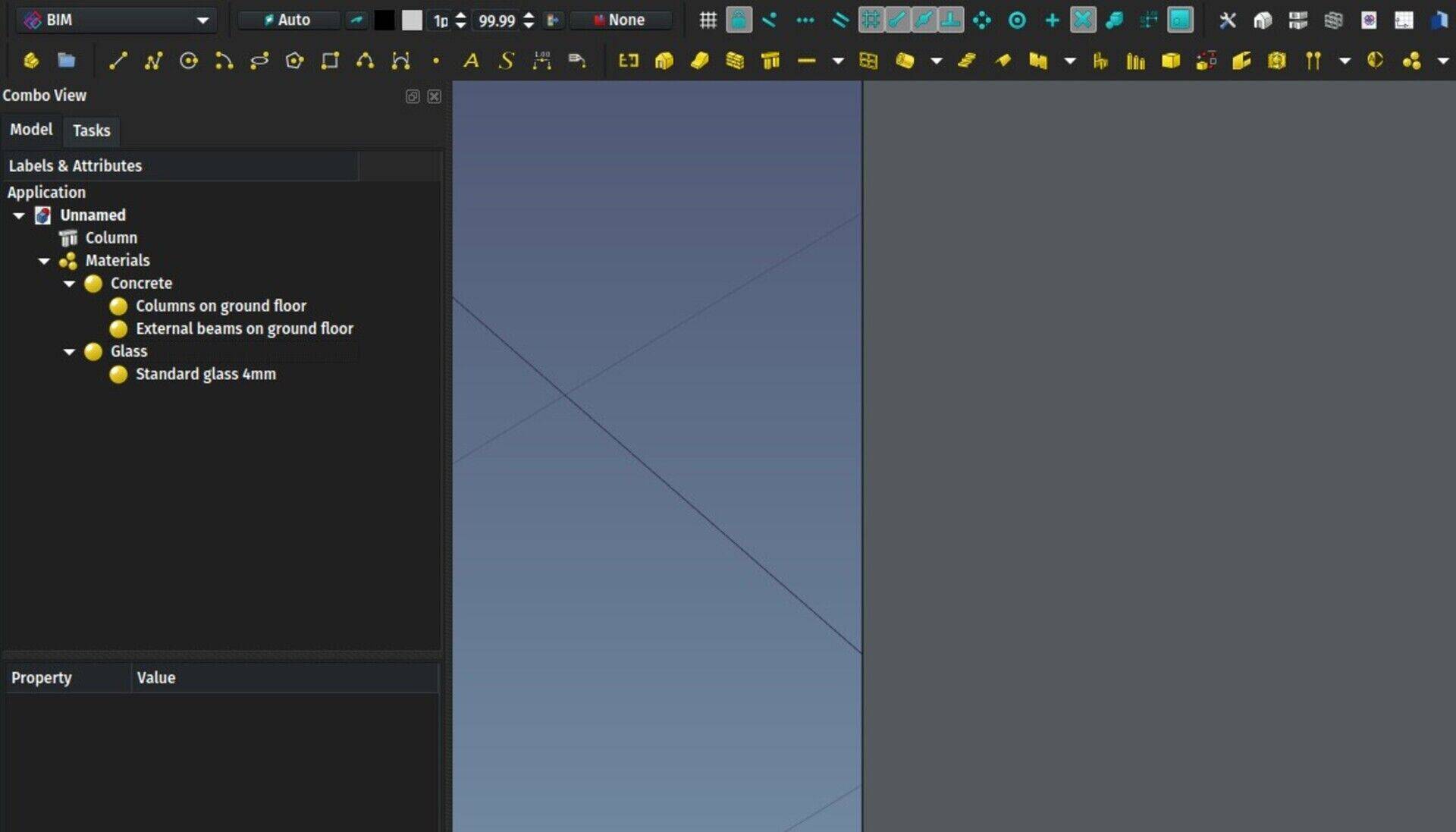
We had some discussions about materials recently, and, since they are used everywhere in BIM, I thought they could be a good way to handle these characteristics and properties that you want to give to several objects at once. In fact, IFC doesn't give you much option to give extra properties to materials, you have to give these properties to each object that uses the material. But we can do better in FreeCAD, and allow materials to have any number of custom properties (that is implemented already). So materials become a kind of "host" for these properties, and on IFC import/export there would be transferred to/from individual objects transparently.
But that means that if you have two objects made of concrete, but one of their "common" properties has a different value, you need two different concrete materials. This will quickly become annoying. So we need a system to be able to have one concrete material, but with sub-materials, which would change only one value, but keep all the others from their parent.
This system existed already in FreeCAD materials, and is now reflected in the tree. You just need to specify which other material is a parent of this one. There is still a lot to implement (additional properties, the ability to remove a value so it takes its parent's corresponding value, support all this in IFC etc), but I think we are on the right track to get an easy and flexible system that won't overcomplicate the model tree.
Part Shapebuilder - Wire from Edges
A simple addition to the ShapeBuilder tool, an option to build a Wire from a selected set of Edges. It doesn't need to be closed or planar.
American Wide Flange profiles and profile edit panel
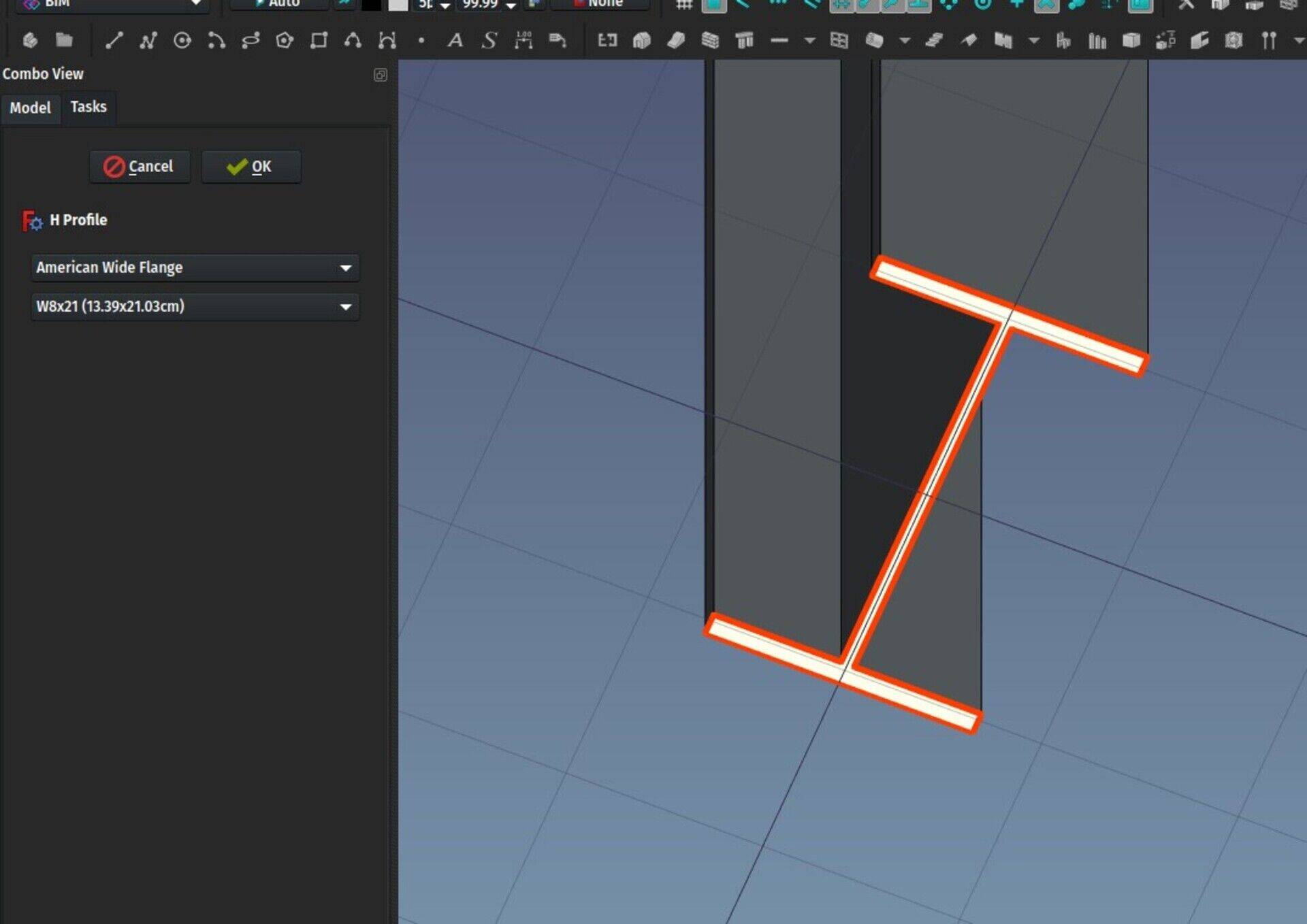
A new series of American Wide Flange steel profiles (W profiles) was added to the Structure tool, and the profile object, that is used structural objects when based on a "built-in" profile, was also upgraded. It now uses an own icon, and it has gained an edit mode panel where you can change the profile definition.
At the moment you can only change to another profile of the same type (H, rectangular, etc...) because I am not sure it is a good idea to permit cross-type changes, model-wise (it will need another object, which as consequences on your whole model hierarchy), but we need to study that point further.
Support of classification systems
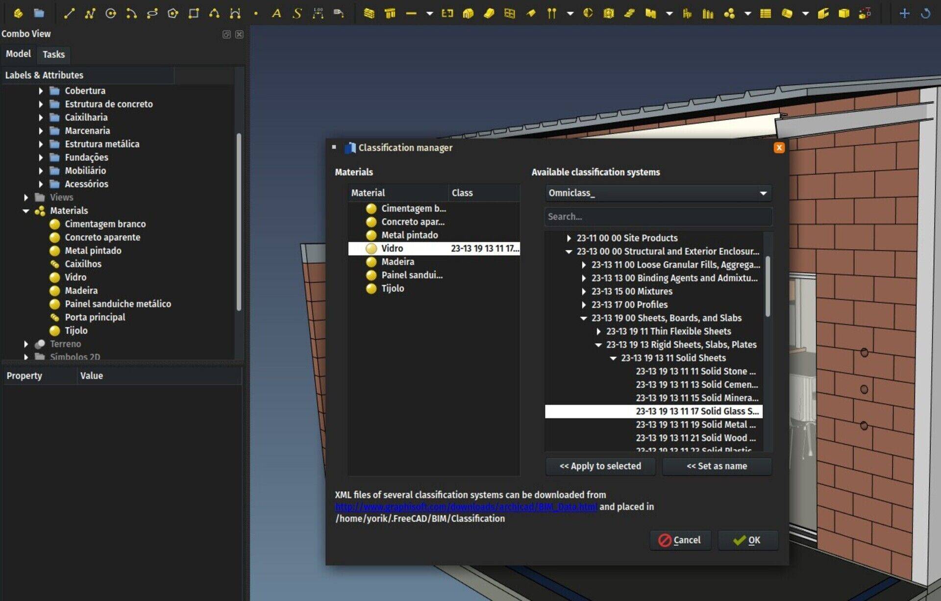
This is another rather simple to implement but major improvement. Classification systems are common since quite some time in the construction world. Basically instead of your own description like "concrete pavement tile for exterior use", you would use a number from a classification system that has an " 01 Exterior pavements" categories, with a subcategory " 03 tiles" with different categories for " 05 concrete", " 06 stone", etc. So your number would look like 01 03 05. You get the idea.
That way, you can give your file around, and there is a much higher chance that everything will be correctly understood, even by people in different countries, as the whole system can be faithfully translated. This is not used much for small projects of course, but think of stadiums being built in other countries, you might see the interest there can be in such systems.
There are many classification systems in use around the world already. Most of them proprietary unfortunately (you have to pay to obtain them), some open and free, and most countries are also developing their own which might or might not be compatible with others. In other words, this is a jungle 
In FreeCAD, materials already had a "Standard Code" property, which can hold any text value. Now, all BIM/Arch objects also have a "Standard Code" property. The idea would still be to use materials for that, but you would be able to override the material code for any individual object.
Last month I stumbled on this repository made available by Graphisoft with many of the most used standards available as xml files (an open format). So now in the BIM workbench we have a Classification Manager tool, that is able to read these xml files, and set the Standard Code property of a material or BIM object with any its values.
So far this is not exported to IFC (I still need to understand better how it works) but we have a fairly decent classification system in FreeCAD already!
Note that these xml files are provided there by Graphisoft on their own good will. We cannot include these files in FreeCAD because they don't have any license allowing us to do so, so the responsibility to download and use them is yours (how to do it is explained when you open the Classification Manager in FreeCAD). They might change their system or simply remove those files anytime. Some of these, however, such as GuBIM, are open-source, and also provided on the website of their author. So it's important to keep fighting for open standards that we can really rely on on the long term.
BIM copy and BIM clone
Finally another small experiment: In the BIM workbench, there is one new tool beside the Move tool (which is the pain old Draft Move tool): A copy tool. It is simply the same Move tool, but with its "copy" option turned on by default. I think it is pretty handy, so you can start it by another shortcut (C,P instead or M,V) and perform a copy instead of a move. One click or key press less.
And another one, the Clone tool in the BIM workbench now works differently than the original Draft Clone tool: Immediately after creating the clone, the Move command is launched so it works more like in other applications: you select an object, press the clone button, and drop the clone at some other location (since you rarely want the clone to stay at the same place of its original).
I am not sure yet if these changes should go to Draft or not. Tell me what you think!
So that's it for this month, once again thanks a lot if you are supporting this effort, one step closer to our dream BIM application!
Cheers
Yorik


 Abraços
 FreeCAD BIM development news - June 2018
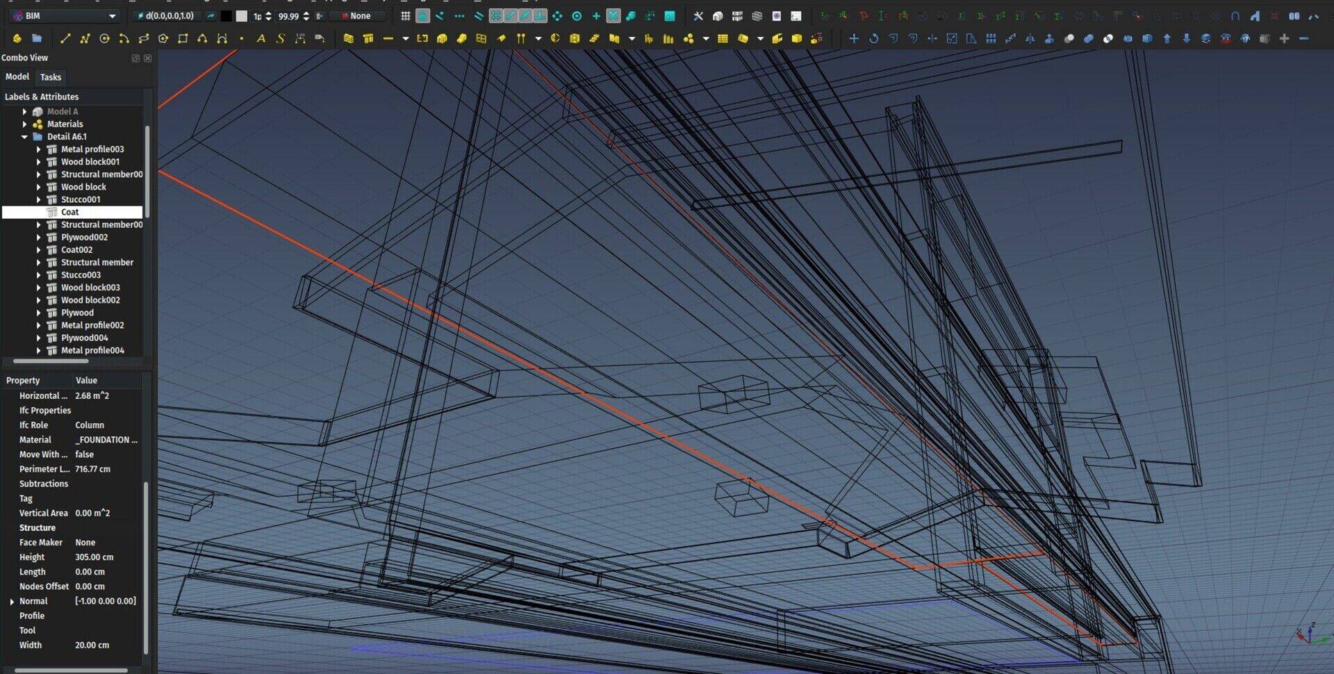
Hi all,
Time for a new update on the development of BIM tools for FreeCAD. There is some exciting new stuff, most of it are things that I've been working for some time, that are now ready. As always, a big thank you to everybody who helped me this month through Patreon or Liberapay! We are very close to meet our first goal on Patreon. We would actually already be there if we sum up both platofrms, so next month I'll lower the goal accordingly and declare it achieved and set everything up accordingly!
So here go the new stuff of this month:
The video
This month's video is a presentation of the new BIM workbench, so in next videos we'll use it instead of Arch. As always, your comments are highly welcome (here or directly in youtube comments).
You will remember last time that I told you about the impressive series of FreeCAD-related videos made by Regis, you might also be interested in this other very nice series about BIM and open-source, with a very large part dedicated to FreeCAD, made by Nirbhay, another well-known member of the FreeCAD community. We begin to have pretty decent FreeCAD BIM learning material!
BuildingPart
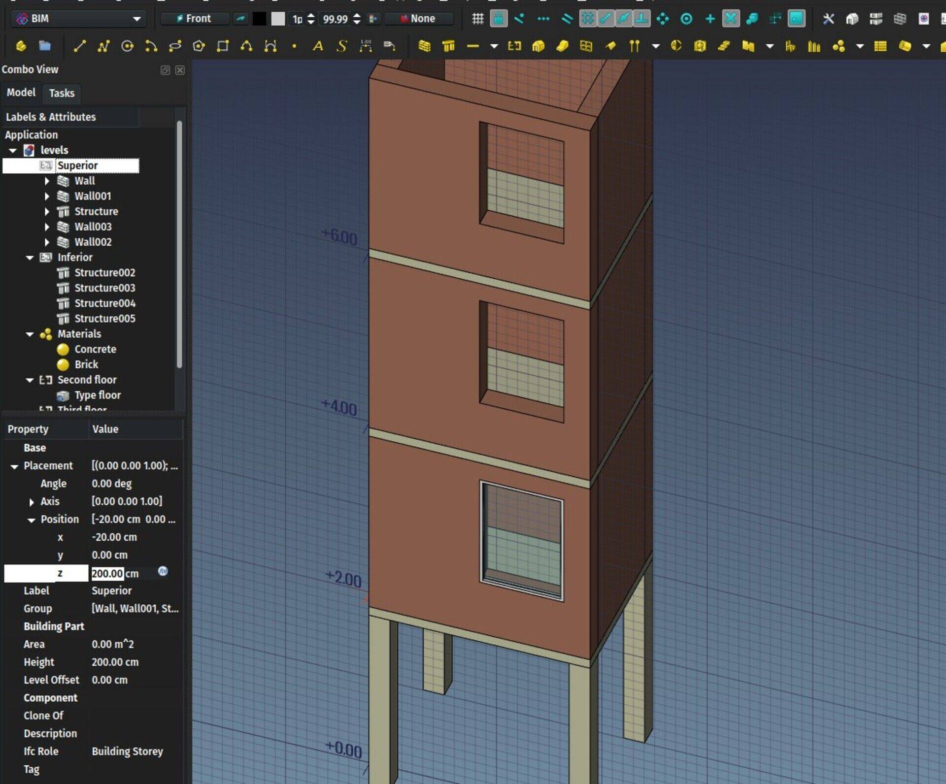
The BuildingPart object I have been working on during the last months is finally ready and is part of the Arch workbench already. It is meant to replace the Arch Floor tool. For the time being, the Floor button is still there in Arch, but it already produces a BuildingPart object with its IFC role set to "Building Storey".
The BuildingPart object is still based on a classical FreeCAD Group object. I played a lot with the idea of using an App::Part instead, because it looked interesting because of its ability to automatically move its contents when you move it, and also that you can make it "active" and automatically add contents to it.
However, I discovered that it was relatively easy to reimplement these two features in another object, and also met some particularities that made me decide against using the App::Part:
The App::Part only allows its children to be part of this App::Part. They cannot belong to any other. This, summed with another particularity, which is that all descendents of an App::Part also become its direct children, makes it impossible to use, for example, a same profile to build two columns placed in two different App::Parts, since the profile will become a direct child of the App::Part. This is not of big importance when designing, for example, mechanical parts, but is very common in BIM.
When you add objects to an App::Part, then move the App::Part, the Placements of the objects don't change. Only their visual appearance gets moved. So if you build a column on the ground floor, then move its containing App::Part 3 meters above, the internal coordinates of the column still indicate the ground floor. And when you remove the column from the App::Part, it pops back to its original location on the ground. This is all "fixable" of course, there are methods in place to obtain the "summed up" placement of the column + its App::Part, and you can add code when removing the column from its Part to deal with the change of location, but this all seemed to me like trying to patch up something that's not really made for that use case.
For part design workflows, this is exactly what you want: Draw your elements at (0,0), then add the to the Part, then move the Part around. If you remove elements from the Part, you want them back to (0,0). You want their internal coordinates to reflect that. In BIM workflows, I think we prefer all our elements to have real-world coordinates. Tell me in the comments if you have a different opinion!
So the BuildingPart is basically a Group, like the old Arch Floor. But with a lot of enhancements:
It can display a "mark" in the 3D view that shows the origin point and optionally the label and level (its z coordinate) . If you move the BuildingPart in Z direction, the level updates. You can give an artificial offset value, so for example if the offset value is 700, but your level is at z = 30, the displayed level will be 730. This is useful to work with geographic coordinates and elevations. You can also select the BuildingPart by its mark in the 3D view.
It can be made "active" by double-clicking it, like an App::Part. When a BuildingPart is active, all new objects will be added to it automatically, like the App Part or PartDesign Body.
When moved/rotated, all its children that either have no "Move With Host" property, or have it turned on, will move/rotate together.
When moving an object out of a BuildingPart, it will keep its current position, not "pop back" to its original position (different from App::Part)
It can be cloned. Internally, the BuildingPart stored a Shape, which is a compound of all its direct children. This shape is used by the clone, also keeping individual face colors. This shape is also stored on disk when saving the file, I think you'll be able to guess where we're heading for next

It can take any IFC type, like other Arch objects. The idea behind the BuildingPart is not only to serve as a Floor/Level/Storey, but to group BIM elements in any other possibly useful way in a replicatable manner. One obvious use would be to make a typical storey of a tower, then replicate it for the other floors, but we can also think of other replicatable things like a toilet stall, a wikihouse component, etc.
It can set the height of included walls and structures automatically. The Arch Floor could do that already. If a height value is set for a BuildingPart, any wall or structure inside it, that has its Height value set to zero, will adopt the BuildingPart height.
It defines a working plane automatically. When double-clicking a working plane, in the tree view or the BIM views manager, the working plane will be placed on the XY plane of the BuildingPart. Later on, I'll also implement the same functions that the Draft WP proxy has, which is to be also able to restore a view angle, and show/hide other objects.
So the idea here is that you would be able, for example, to double-click a BuildingPart which represents a level of a building, and set yourself automatically in top view above this level, hide all other levels, and set the working plane to the floor plane of this level, just like if you were working in a 2D plan. When deactivating that level, you would have everything turned back on, and pop back to the view you were at before activating.
But I found it safer to go step by step, and let people play a bit with the BuildingPart first, before implementing more stuff.
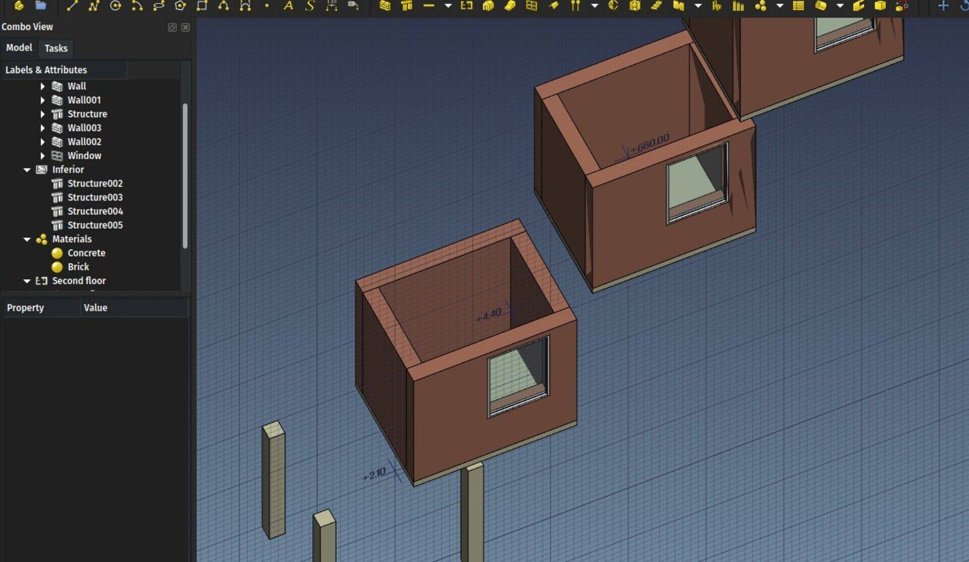
Blender importer

This is another big thing I have been working on for many months. It stayed a long time on hold because we were waiting for FreeCAD to reach a good Python3 compatibility. This is now done thanks to the hard work of several FreeCAD developers, specifically looo and Werner (and a bit of myself too). The issue there is that Blender only uses Python3 while FreeCAD was still not fully ported to it, but Python2 and 3 modules are incompatible with each other.
The code of the importer currently lives in a gist, but as soon as I get some remaining issues fixed, I'll submit it as an official Blender addon.
You can already use the importer, it is pretty stable already, but you'll need to get your hands on (or compile yourself) a version of FreeCAD compiled with the same Python version you use in Blender. The minor version number must match too, so if for example Blender uses 3.6.1, FreeCAD must use also 3.6 (the third digit can be different)
After that, it's just a matter of saving the code from the gist as a .py file (for example io_import_fcstd.py) and place it in Blender's addon folder, then enable it in Blender's addons preferences. If your Python3-compiled verision of FreeCAD is in an unusual location, you might also need to set its location in the addon's preferences.
This is all still a bit uncomfortable, but with time this will get addressed properly. The important part is that it already works pretty reliably.
You will then get a new option in Blender's File->Import menu to directly import a FreeCAD file. You can set a scaling factor between FreeCAD's internal unit (millimeter) and Blender (at the moment I set the default to 0.001) which will import as one Blender unit = 1 meter, and set a couple of other handy options.
The importer will at the moment only handle Part and Mesh-based objects. That is, basically, no texts and dimensions. Groups are also not yet supported, and either are clones (each comes as a separate object). But the geometry comes pretty accurately. Curved faces will be triangulated, flat faces imported as ngons. Materials are also correctly handled and attributed, and materials have both Blender internal settings and cycle nodes (I stil need to implement a proper cycles transparency node for transparent materials).
There is also one feature that will be specially interesting in viz work: The ability to replace objects with similar names. FreeCAD holds an internal, unique name for each object. Blender doesn't have that feature, but has something similar, where an object holds a mesh that can have a different name.
So what happens now is that the Blender object name is set to the FreeCAD object label, while the mesh name takes the FreeCAD object unique name. This allows to match each FreeCAD object with a corresponding, unique Blender object. If you enable the appropriate option when importing a FreeCAD file, if a corresponding object is found in Blender, only its mesh will be updated, the current Blender materials will be kept (and reattributed per-face).
This allows you to work on a FreeCAD model, import it in Blender, makes some changes to materials in Blender, setup your scene, add more objects, etc... Then reimport your FreeCAD files, and keep the object positions and materials that you changed in Blender.
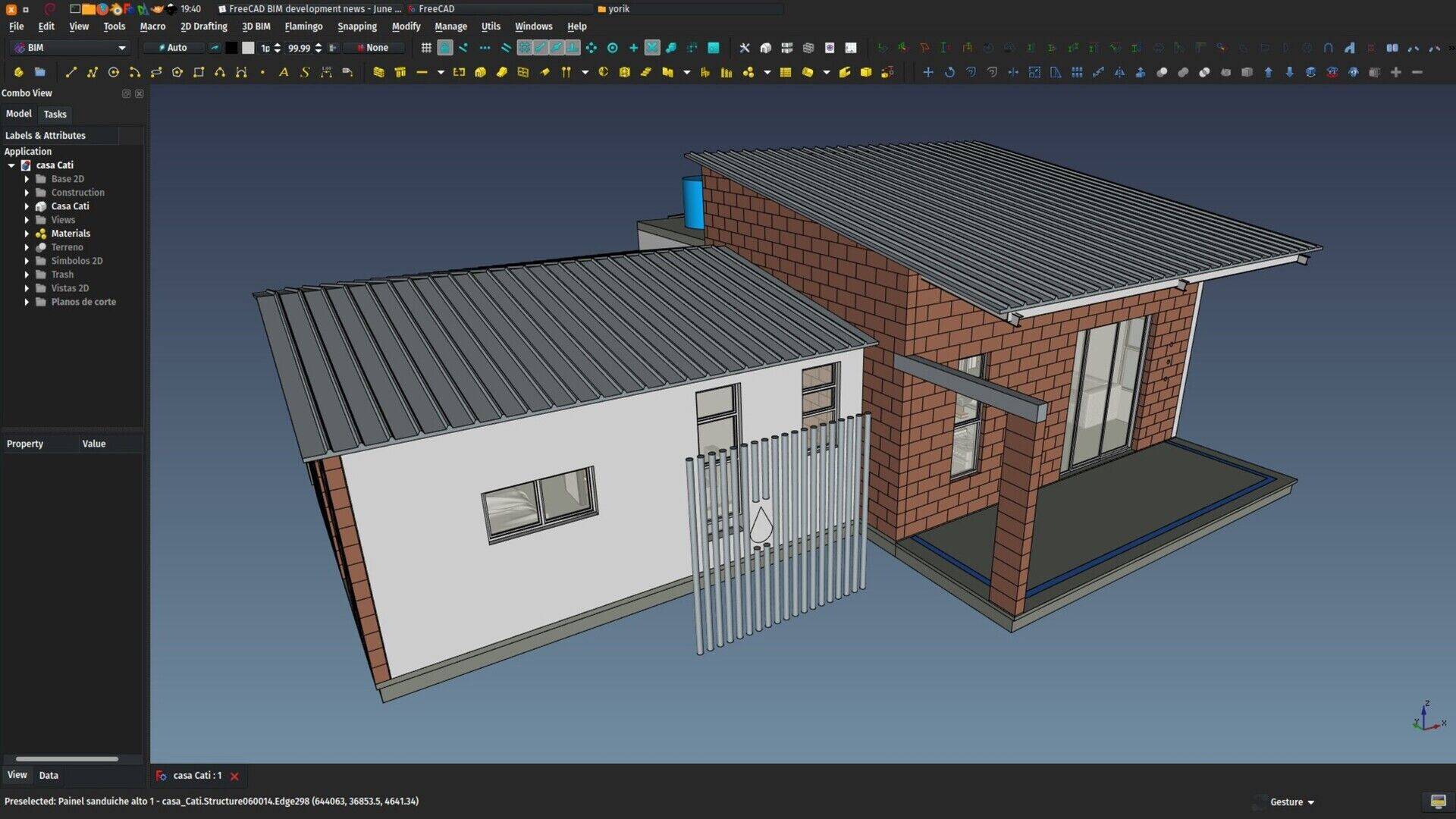
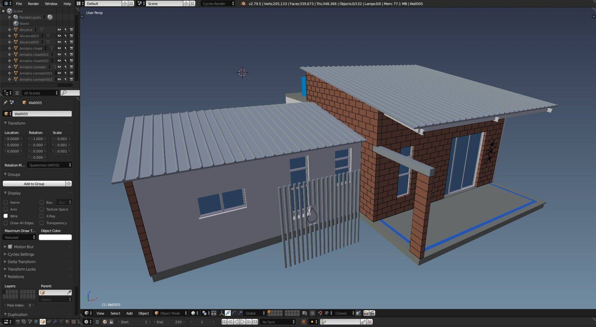
Arch objects now check their properties at file load
This is a small change, but that will be great for backwards and forwards compatibiliy between different versions of FreeCAD. Basically objects loaded from an older file will now have their properties updated when loaded in a newer version of FreeCAD, so they'll be albe to use all the new features.
In the same way, objects loaded from a file made with a newer version will be able to "auto-fix" to work with this version.
Walls can have their baseline as Draft lines
Walls can already use all kinds of 2D objects as their baseline, but by default, new walls will have their base line created as a sketch. This is not always the most interesting thing to do, in many cases a simple Draft line is more efficient, as it can be edited by Draft tools like Edit or Stretch, which support snapping. So now there is a preference option to make new walls create a Draft line instead of a sketch.
IFC Property Sets
This is still a work in progress and not ready for merging, but it's an interesting subject anyway. In IFC, objects can have custom properties. These properties can be grouped into property sets. At the moment, when reading an IFC file, FreeCAD will read and store all properties of an object, but not the property sets they belong to. So when reexporting the file, properties will loose their property set information.
I tried for some time a complicated way to handle these property sets, but recently found a much easier (json-based) way which will also serve for other things (speckle?). So this part can almost be considered as solved.
There is another interesting feature available in the IFC specification, which are pre-made, or standardized property sets. These define, for example, some common properties for walls, that all walls should have. Same for almost all IFC entity types.
These standard property sets are not mandatory. In fact I have very rarely seen an IFC file that uses them. But using them in FreeCAD would be a very good way to create more standardized IFC files. These property sets are not defined in the IFC schema, so I already coded a small utility to download these definitions from the net, and pack them in an xml file. This xml file will be bundled with FreeCAD, and the IFC property editor I'm working on will be able to use it, so we can easily, for example, add common property sets to our objects.
Dynamic window parameters
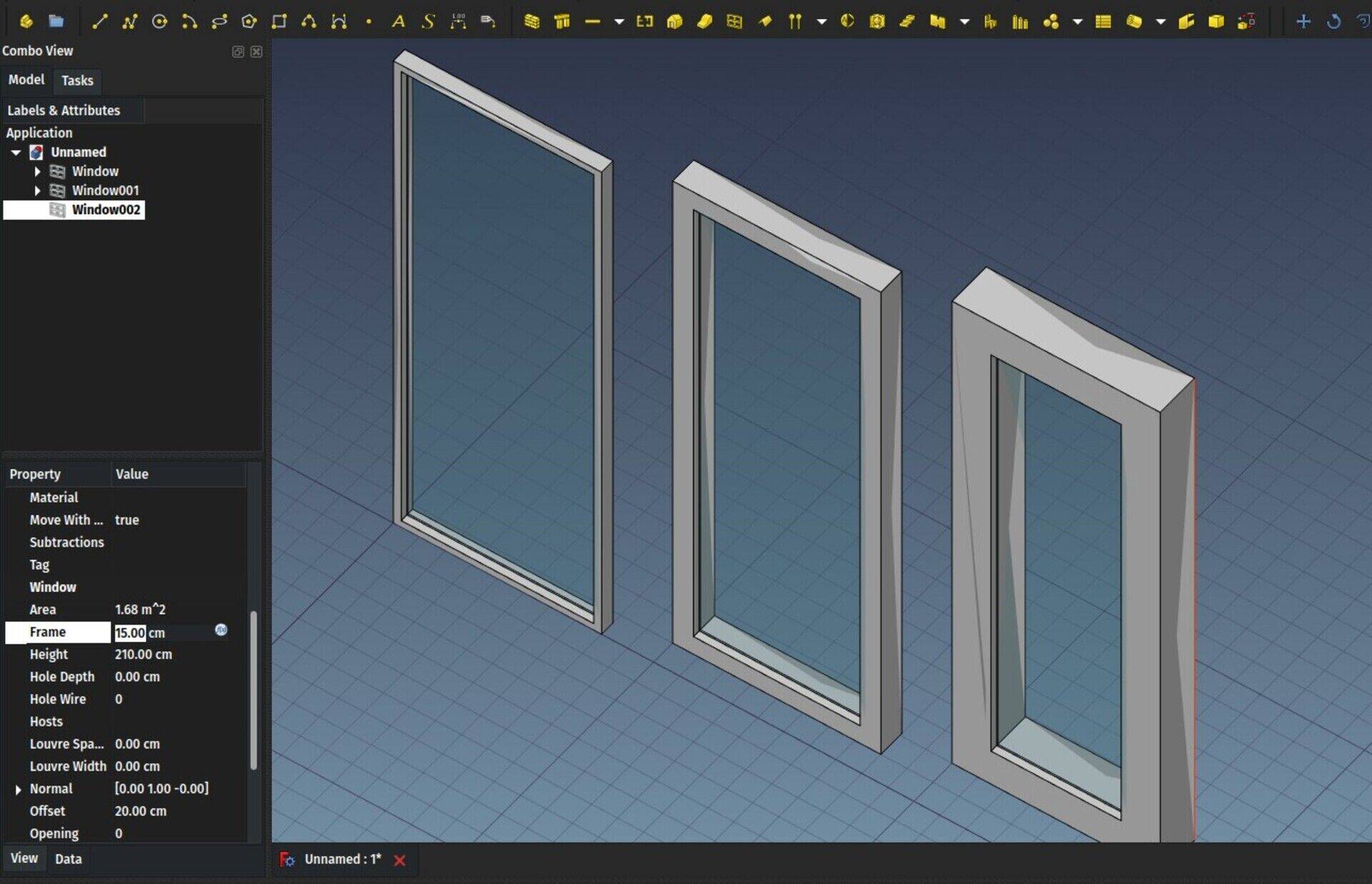
So far, once a window was created, it was possible to change its width and height via its properties editor. To change more advanced details such as frame thickness, you had to edit the window components parameters or the base sketch directly, which was tedious. Now, windows have two new properties: Frame and Offset. As with width and height, changing the frame or offset values will change the window accordingly.
If you wish to use this in your custom windows, it uses the same system as width and height: In the base sketch, if you define two length constraints (horizontal or vertical) and name them "Height" and "Width", they will be controlled by the host window's "height" and "width" properties. To have other length constraints controlled by the "Frame" property, just include "Frame" in their name, for example Frame04.
In the window parameters editor, you now have two new checkboxes to make use of the offset and frame properties.
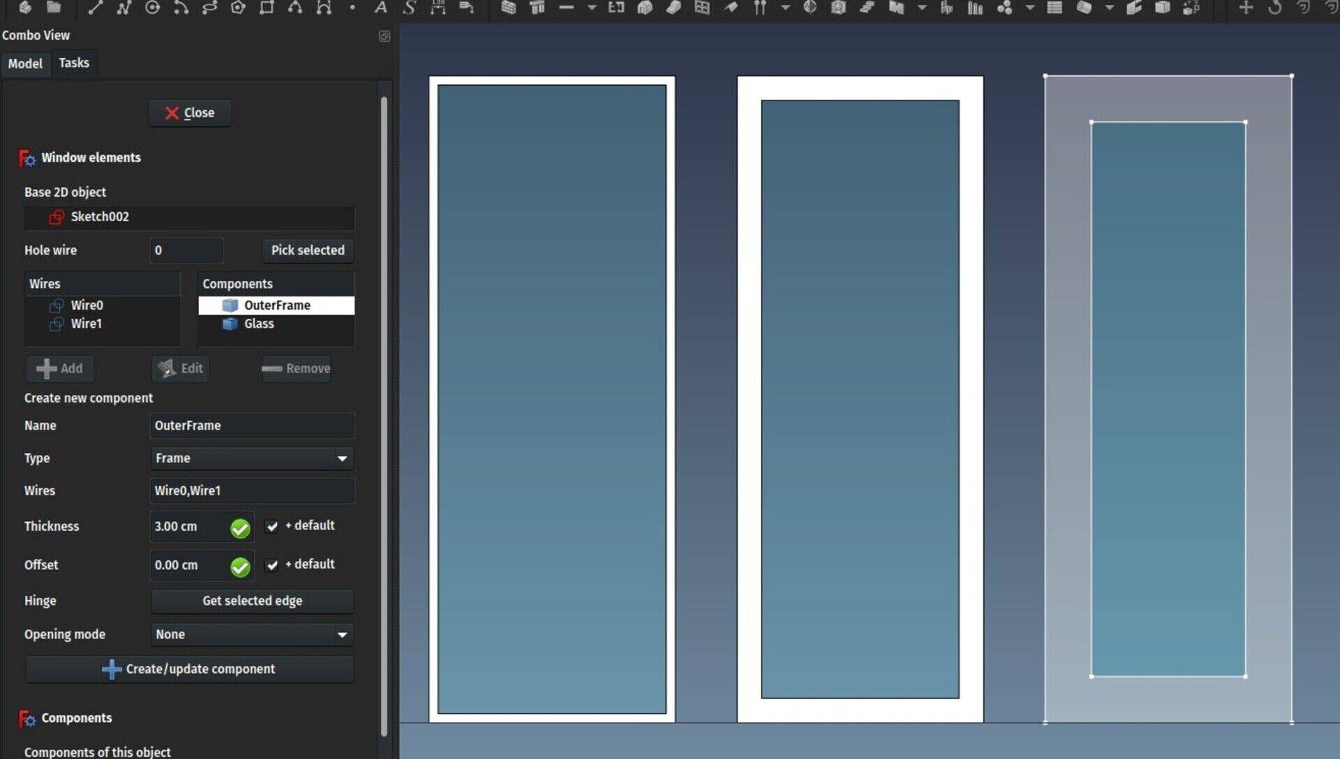
This is not the end of the path of course, but slowly we'll get there to a friendlier window object...
Merge dupliate materials
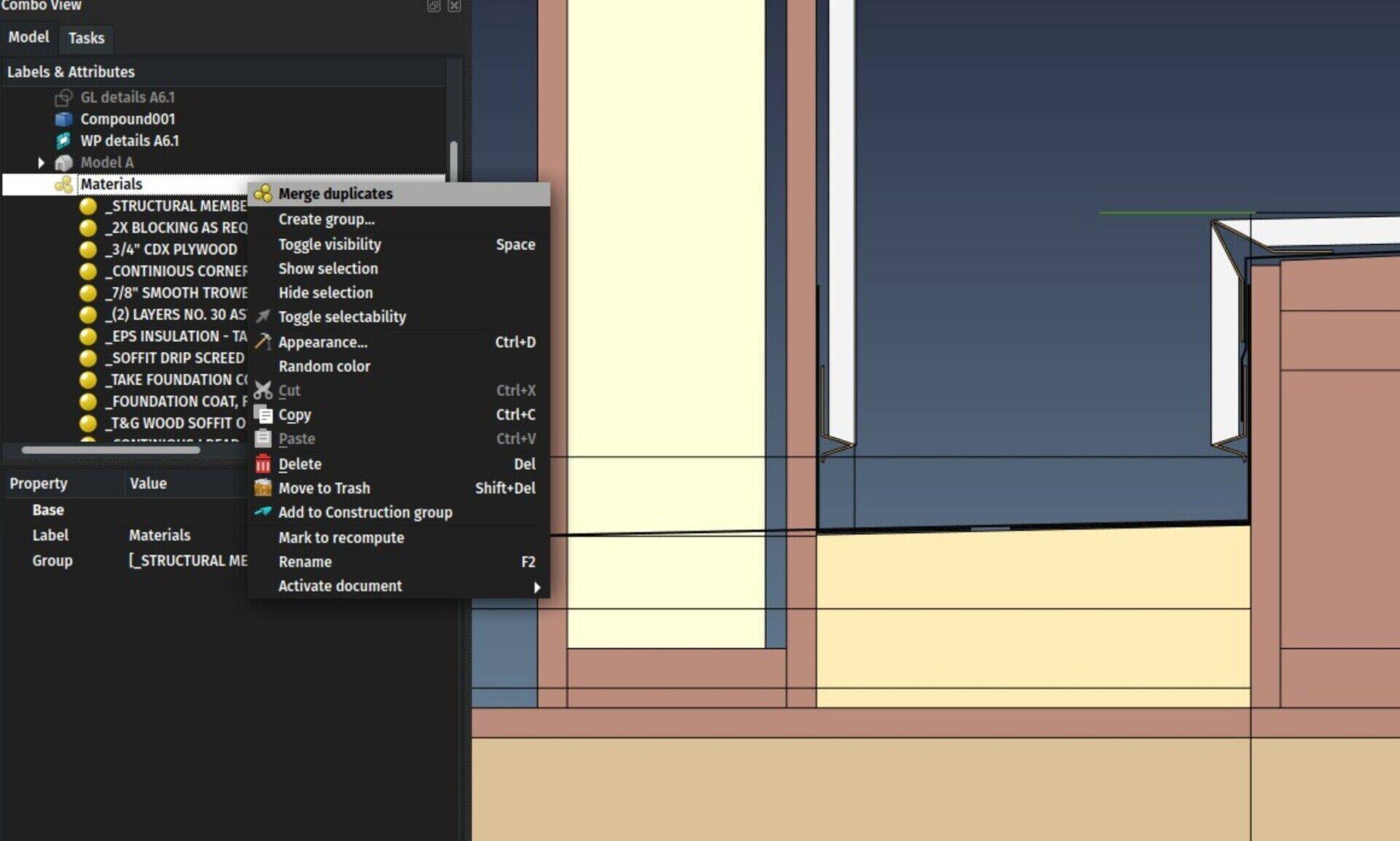
By right-clicking a material group, you now have an option to merge duplicate materials. That is, materials with a same name but with 3 digits at the end. For example Concrete and Concrete001 will be merged. Any object that used Concrete001 will be changed to use Concrete instead. Very useful when importing susequent versions of IFC files.
BIM IFC elements manager now manages materials too
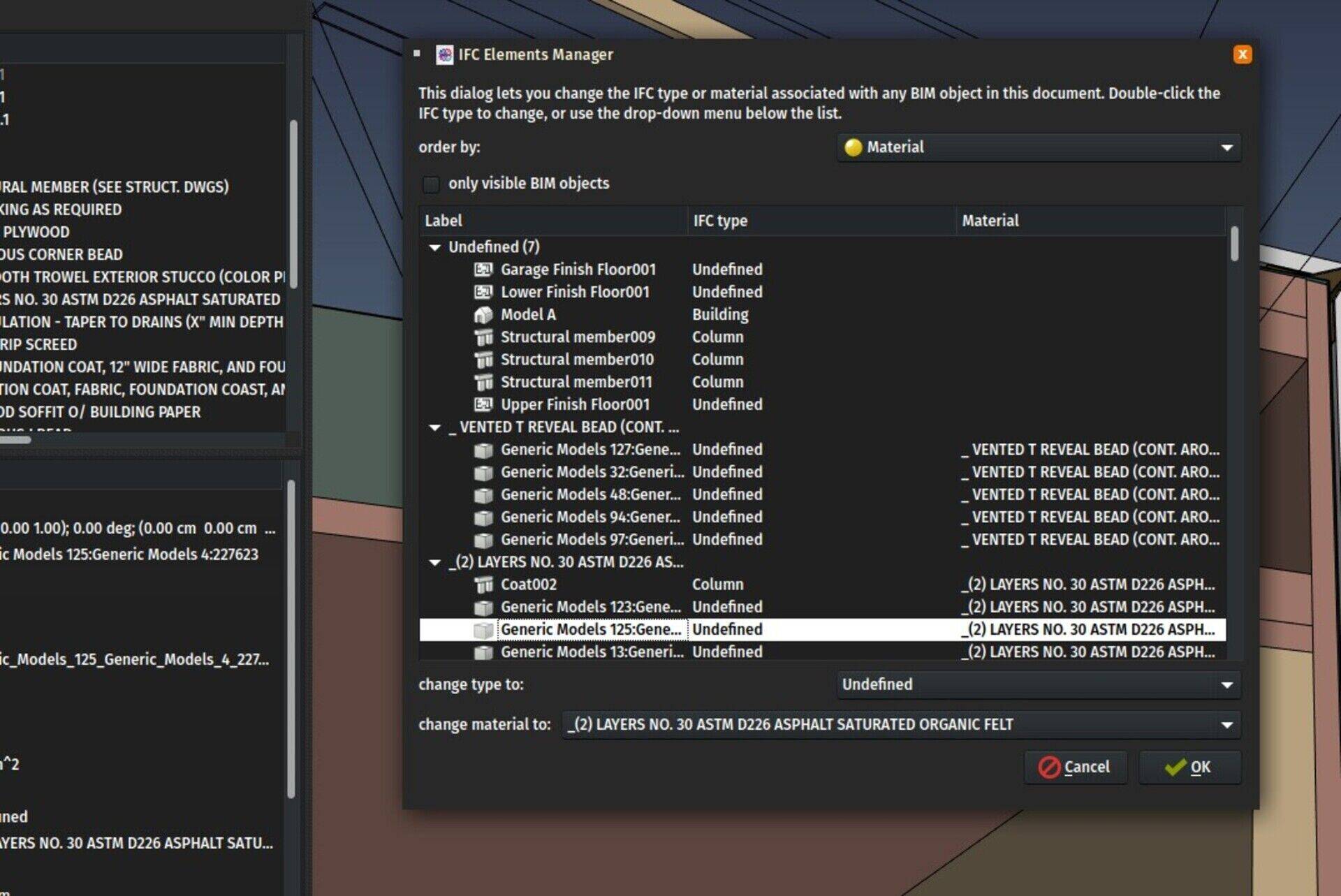
Now this dialog from the BIM Workbench also allows you to check what object uses what material, and make sure you have everything properly configured before exporting to IFC.
 A Sketchup that saves solid models.
Two things, though:
- It is still very unstable, I can easily make it crash in less than a minute.
- It only saves DWG/DXF files. I think it might be time for FreeCAD to seriously attack SAT/SAB format...
http://www.bricsys.com/en-us/shape/
- Ferramentas programáveis - Participação na mesa "Fronteiras da tecnologia na cultura" na UFABC : https://yorik.uncreated.net/archive/talks/ufabc-2018.pdf
- BIM e estruturas prefabricadas: Adaptabilidade, interoperabilidade e formatos abertos: Palestra no 1° seminário Precast Concrete Technology : https://yorik.uncreated.net/archive/talks/pct-2018.pdf


The second point means that any FreeCAD Arch/BIM object (wall, column, door, etc...) can have any IFC type (column, window, pipe, etc...) so you could use the Wall tool to build a table, for example
Second, about the "split the internal functionality into separate toolbar buttons".. i think you can improve it with KEY-COMBS, like shift, alt, ctrl.. etc. that activate different presets when are pressed.
And last, i dont understand what "All objects can have all IFC types" is for (soo newbie meaby?).
Regards
FreeCAD BIM development news - May 2018
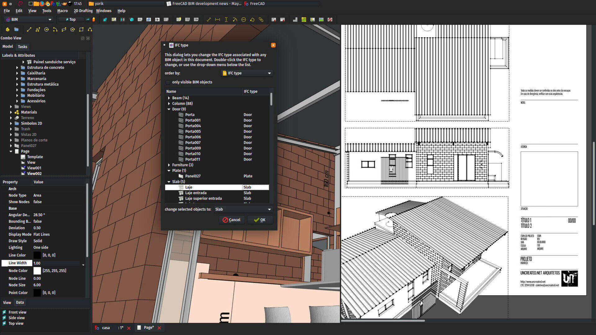
Hi there,
Time for a new update on BIM development in FreeCAD. Since last month saw the release of version 0.17, we now have our hands free to start working again on new features! There is quite a lot of new stuff this month, as usual now, spread between the Arch and BIM workbenches. For who didn't see the previous posts where I explained the idea, I am now basically more and more trying to split BIM stuff between what goes into the Arch module, which is included into the FreeCAD source code, which will contain all the "hard-core" stuff (object definitions) and will probably grow more and more deprecated as a workbench, and the BIM workbench, which will contain all the UI (User Interface) work.
This split has many advantages, mainly 1) to make it easier for other people to contribute to BIM development without the need to dig into the FreeCAD source code, and 2) be easier to experiment, outside of the FreeCAD source code itself.
For the FreeCAD user, these distinctions don't really matter, you should basically now use the BIM workbench, and everything from Arch will be there too.
As always, the time I can spend on FreeCAD is a diret consequence of the help I receive from many of you on Patreon or LiberaPay. Thanks a million to everybody who is contributing already, and if you aren't, what about joining the family?  Also, helping me with a couple of bucks is just one way to help. Python coding is easy, and the Arch/BIM split makes it even easier to get into it. There is a forum thread dedicated to BIM development. All the help is welcome!
Also: Some pleasant things can happen while you work with FreeCAD...
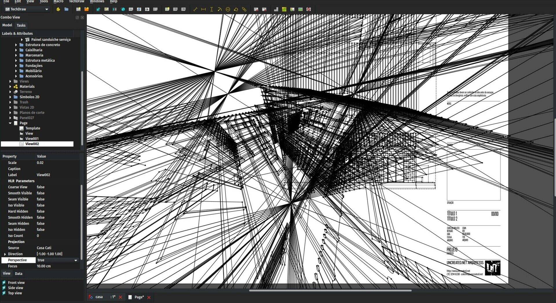
The video
This month, the video is about windows. Hope you'll like!
Arch Panel waves
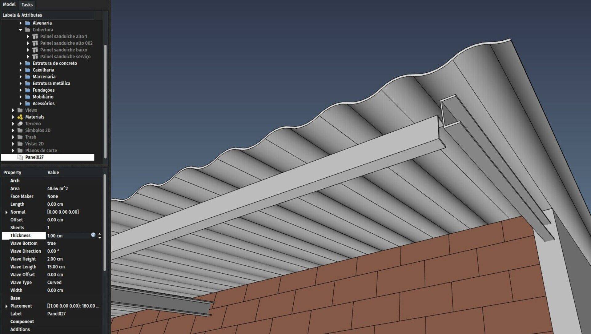
This is an item that was annoying me since a long time and has now gained a good update. Panels were already able to be displayed as a flat plate, or as a corrugated panel. But the system was very slow, because a small curve section was generated, then copied over, then extruded, then unioned to the next curve section, resulting in a lot of boolean operations, which, in any CAD system, are an expensive operation that you as a developer must try to use as little as possible.
Besides, that system didn't do a very good job with multilayer panels, and couldn't have a different bottom face, which is both common in sandwich panels and convenient when you don't need to show the curves on the bottom face.
Both these issues are now solved. Now, internally, the code generates one big profile for the whole panel, which is then extruded and doesn't need to be unioned anymore, which makes it way faster to calculate. Additionally, there is one more wave type ("spike"), and you can make the bottom face flat.
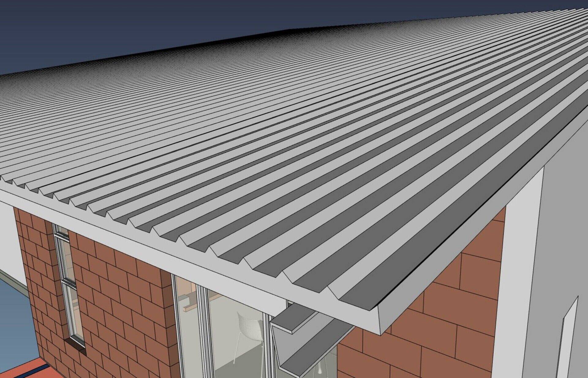
Beam drawing mode
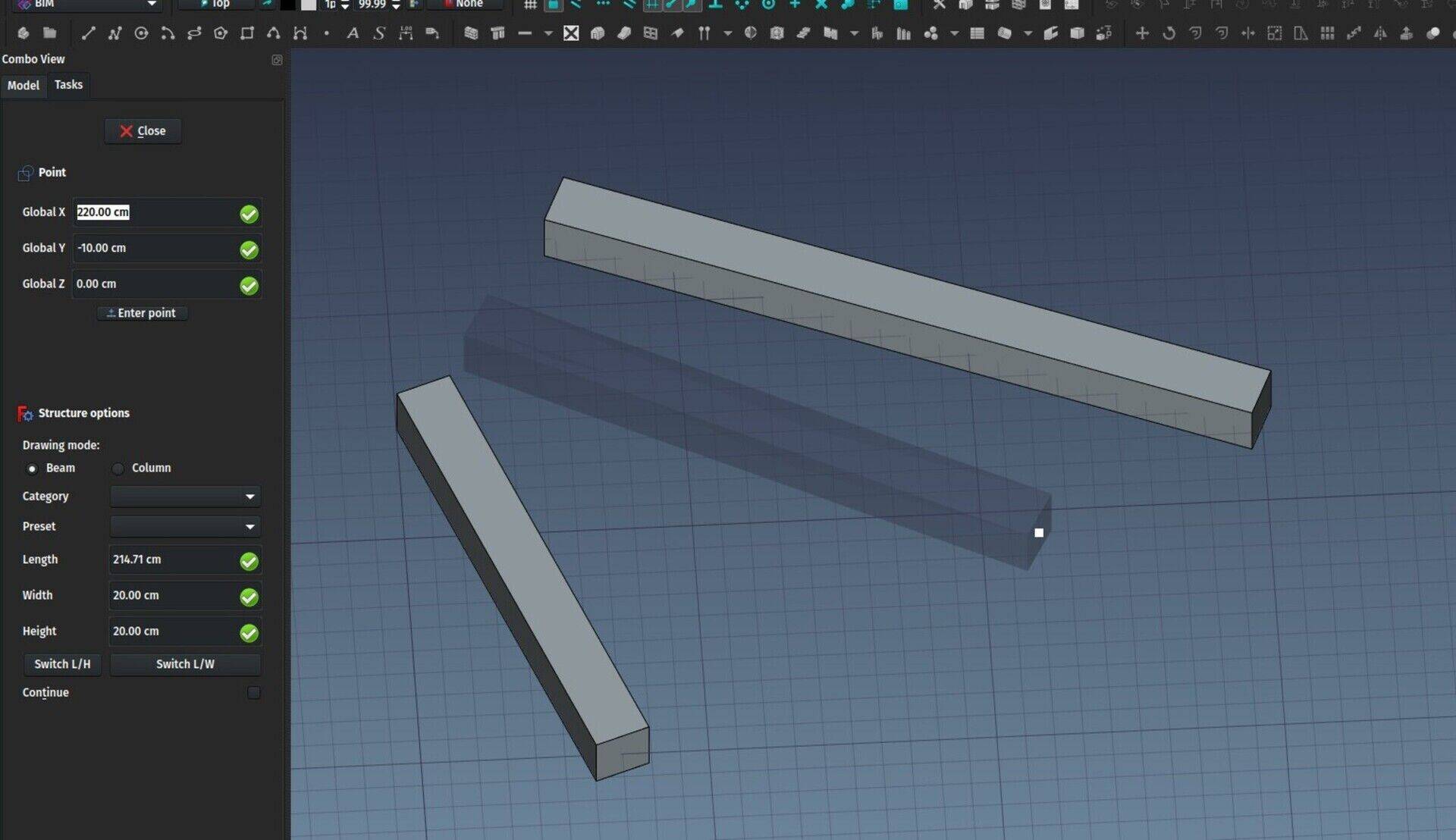
This is another long-time request, it is the ability to "draw" beams directly in the 3D view, like walls. So now, when pressing the Structure button, you have an option to switch to that beam drawing mode, instead of just placing an element. I'm not too happy about that interface yet, it seems annoying to me to have to click that control to switch modes, but it is more important to have the tool to work well first, sooner or later an idea will arise to make the UI workflow better.
Another related idea I am always toying with, is if it wouldn't be more interesting to split the "internal" functionality offered by the different BIM tools into separate toolbar buttons, in other words, less complex tools, more toolbar buttons. For example, instead of one Window button that has 6 window presets, have 6 window buttons, each running a different preset. I have no clear idea about that yet, I am not convinced that it is an interesting trade-off, it seems to me it's only moving the compexity to another place...
More thinking is needed there 
Draft scale reference mode
The Draft Scale tool, when I coded it, was very remotely molded upon the AutoCAD scale tool. One feature I used a lot in AutoCAD was reference scaling. You take one distance, and you say "I want this distance to become that other distance". But this made the Draft Scale tool horribly clumsy to use, specially with 3D objects. In fact, nobody was using it and people were using the Clone tool, which allows to set a scaling factor in an easy and intuitive way like (2.0, 2.0, 2.0) for scale factors on the X, Y and Z axes.
So a while ago I remolded the Scale tool to have the same, simple system. Now you choose your objects, set the scale factor, and choose if the result is a Clone object, or if the original objects must be modified directly (this doesn't work for all object types ATM).
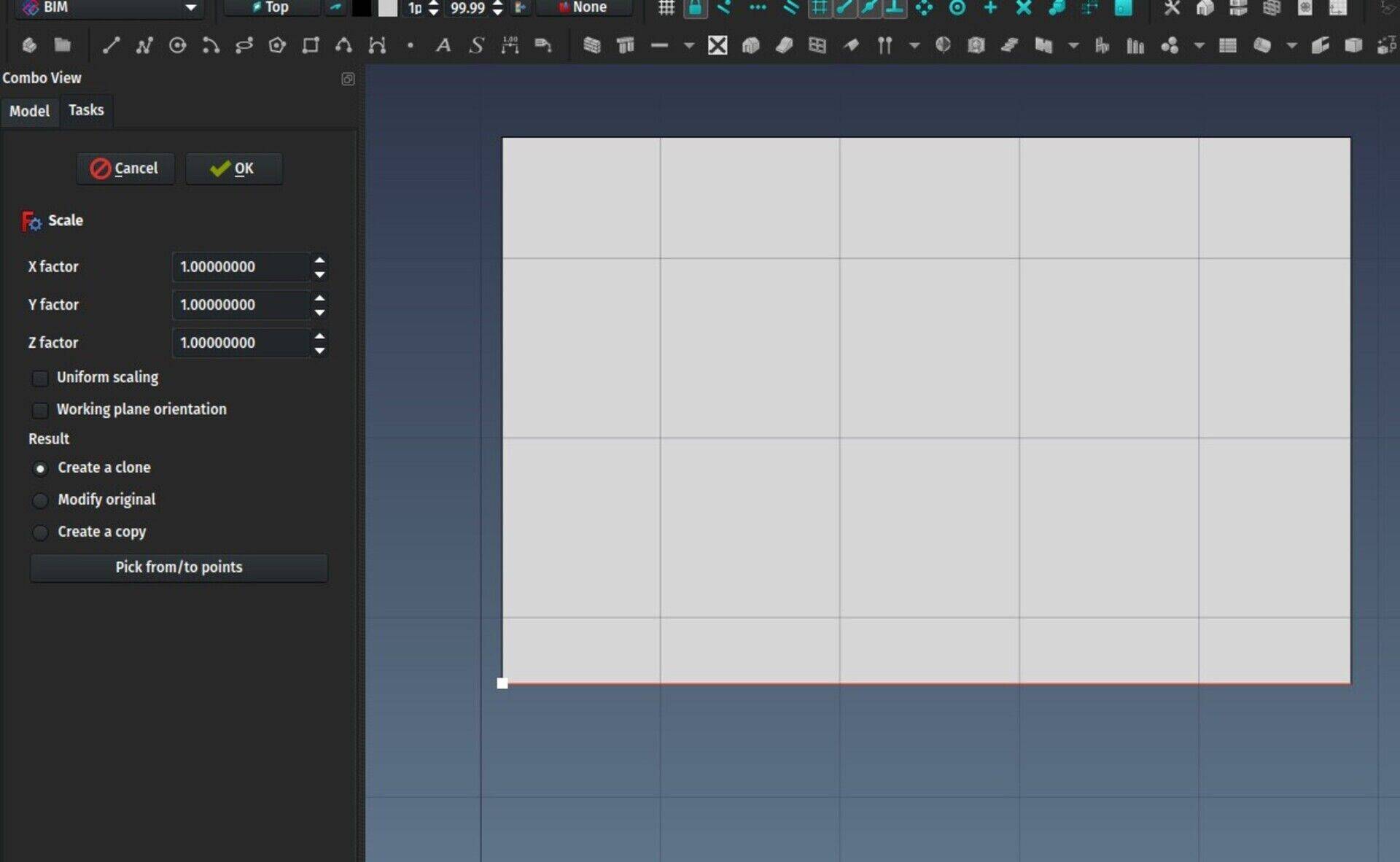
Now we finally have the best of both worlds: The scale tool still works the simple, reliable way, but you can also define the scaling ratio by picking a reference distance and a target distance in the 3D view. The scale factor will be the ratio between these two distances.
All objects can have all IFC types
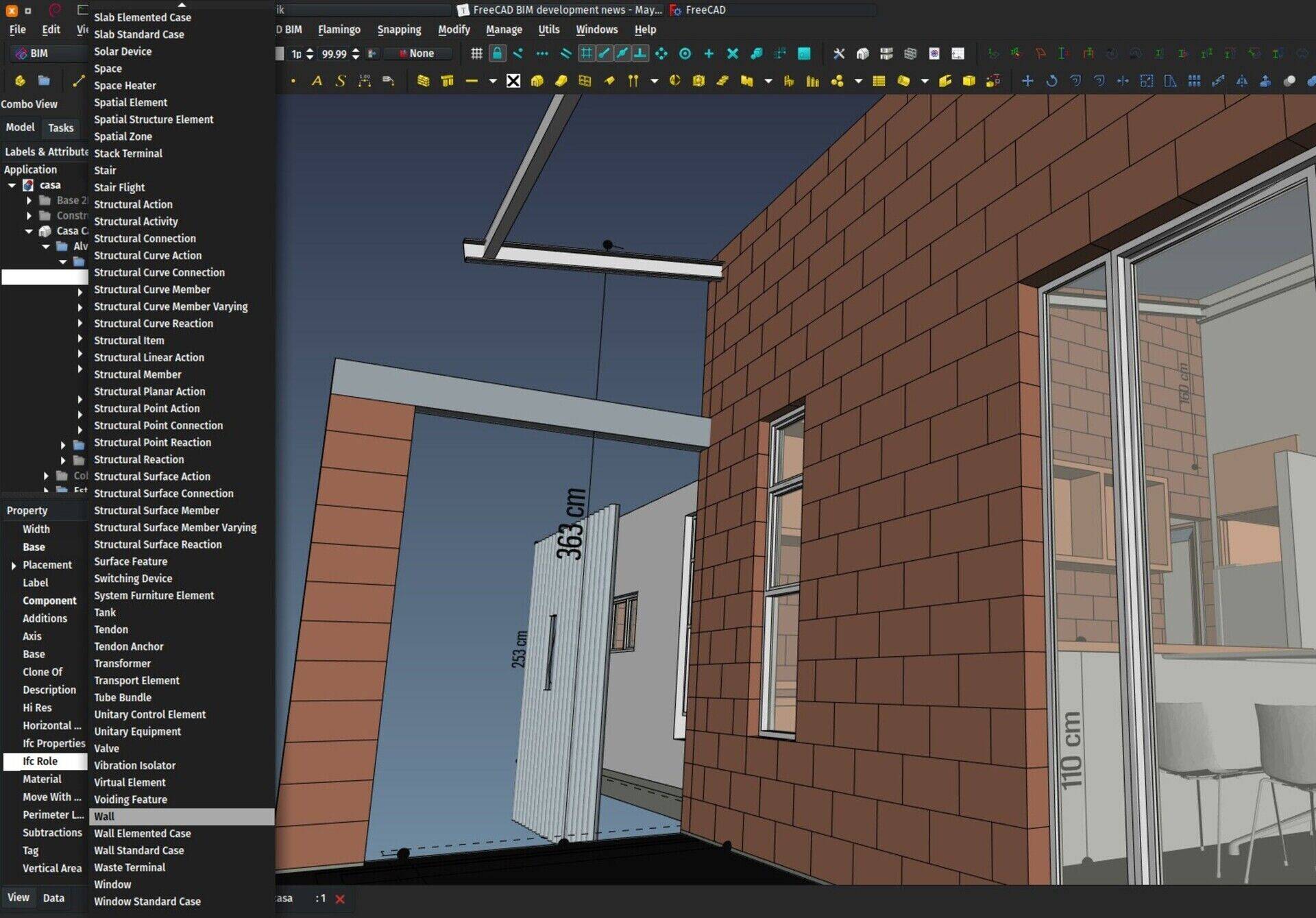
This is a very simple change, but that open large possibilities. All Arch objects already had a "Role" property that could be used to fine-tune the use of each object, for example a Structure could have its Role set as Beam, Column, Slab, etc.. But this was basically not used anywhere, except when exporting to IFC. And each Arch object type has its specific list of possible roles.
Now the Role property has been renamed to IfcRole (this is part of a larger effort I am beginning, to group all Ifc-related properties into some specific group), and it can take any IfcProduct role. The IfcProduct is the master class of all "physical" (and a couple of non-physical ones too) elements found in a building, such as column, wall, door, etc (full list here).
In other words, from now on, any Arch object (or, in fact, any FreeCAD object, as you can just encapsulate it in a Component) can be exported to any IFC type. This is something surprisingly simple, offered by very simple apps like Sketchup, but that is curiously hard to do in many BIM applications...
Draft Text object
The Draft Text tool, until now, was using a basic App::Annotation object, which was not very handy to use and lacked a couple of features. Now the tool is using its own python object, which is much more comfortable to work with. The two immediate results is that the text object now has a placement, so it can be rotated and placed in any custom position you may want, and it is now a common scene node, so it won't appear through other objects anymore, like the old object did.
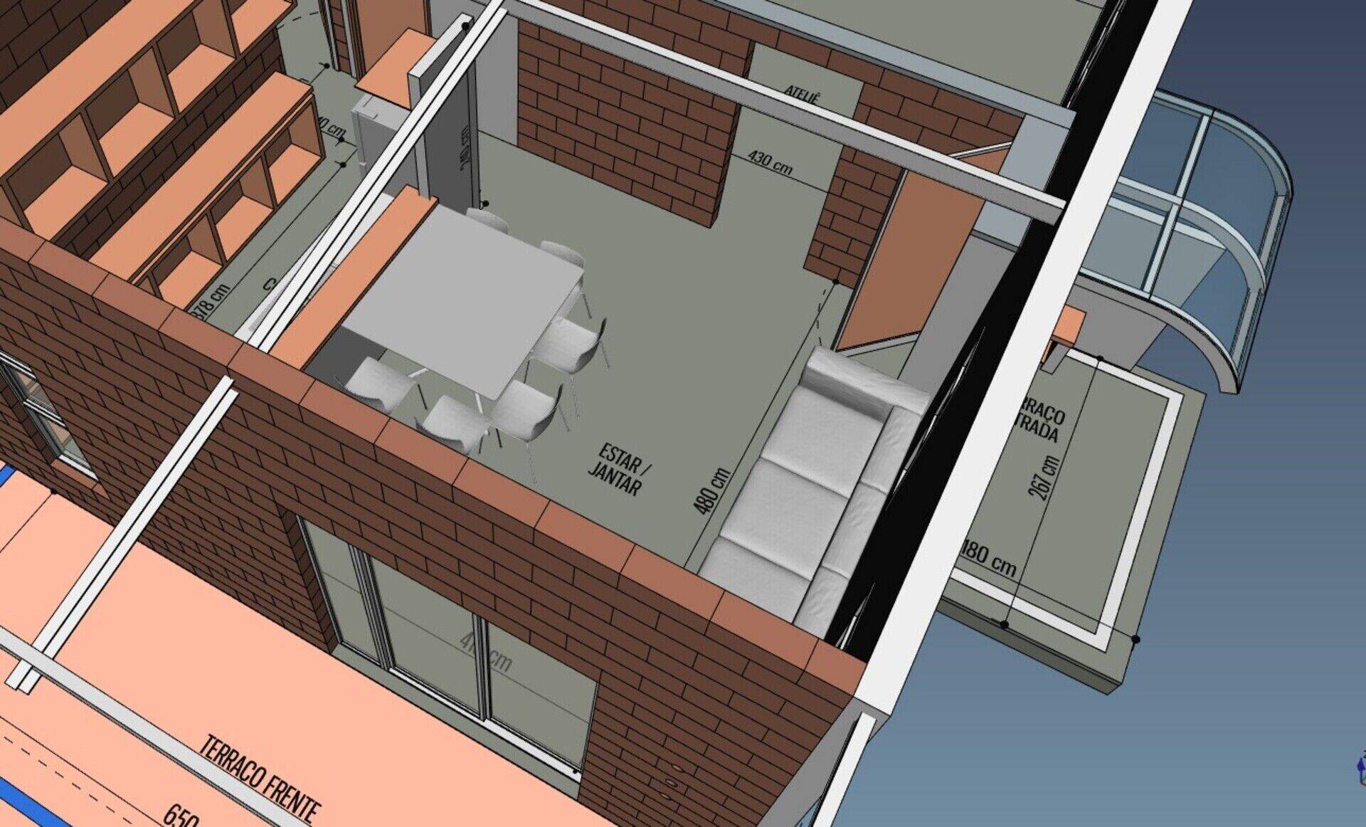
From python, you can use Draft.convertDraftTexts() to convert old-style Draft texts in a document to the new format.
BIM IFC elements manager
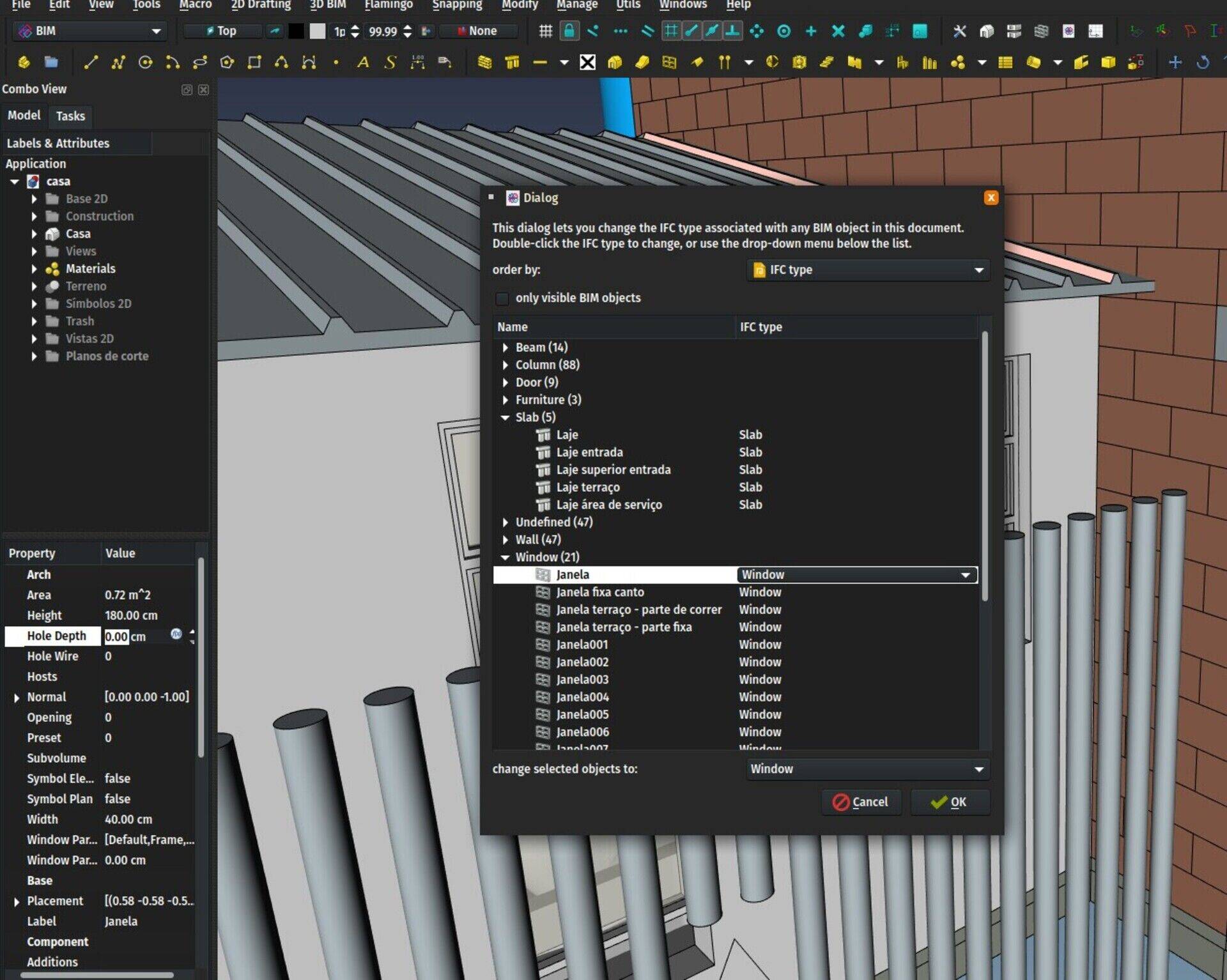
A new "manager" tool is now functional in the BIM workbench: The IFC elements manager. What it does is basically shows you all the Arch objects of your document, together with their IFC role. Here you can easily manage all these roles individually or several at once, and make sure everything will export as you want. That screen also allows you to rename objects.
Better window placement
Accurate window placement has always been a pain in FreeCAD. So much that me and others ended up advising to disable snapping when placing windows, then reenable it and move the window to its correct position. Hopefully, thanks to a very simple change, this is history.
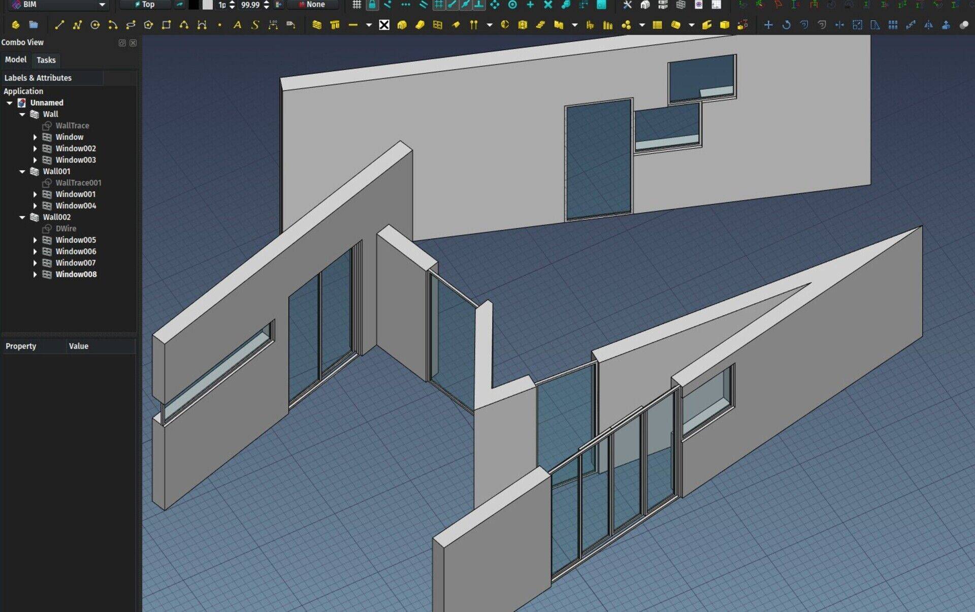
Now, when placing a window, when hovering with the mouse over a face, the window will take and keep the orientation of that face, until you hover on another face. This allows to both align a window to a face, and take advantage of the full snapping tools, for example to place a window on an edge or a vertex, like one would expect.
This is not yet 100% perfect, one would still like to be able to place a window at a certain position relatively to another element, but this is a larger question that relates to other elements too like walls or columns. In any case it is already a good step forward, now the window tool finally works properly.
Flatten wire option
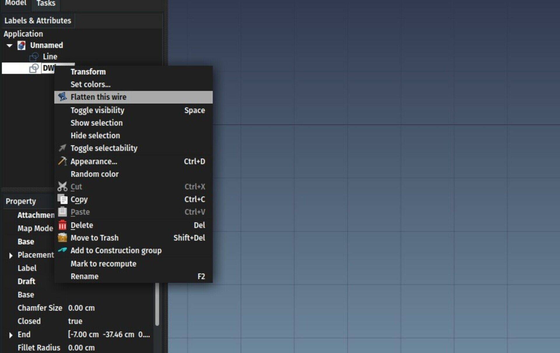
It can happen, when working with Draft Wires,that the wire is not exactly flat. Nothing in FreeCAD or OpenCasCade prevents that. But it might not be usable to form a flat face anymore. This is specially often the case with geometry that you import from other applications, where rounding could occur. The DraftGeomUtils module already had a flattenWire() function that would project all the points of the wire onto its median plane. Now, a right-click context menu option has been added to Draft Wires to perform that action, so it has become a piece of cake to fix those problems.
New AutoCAD-like prompt
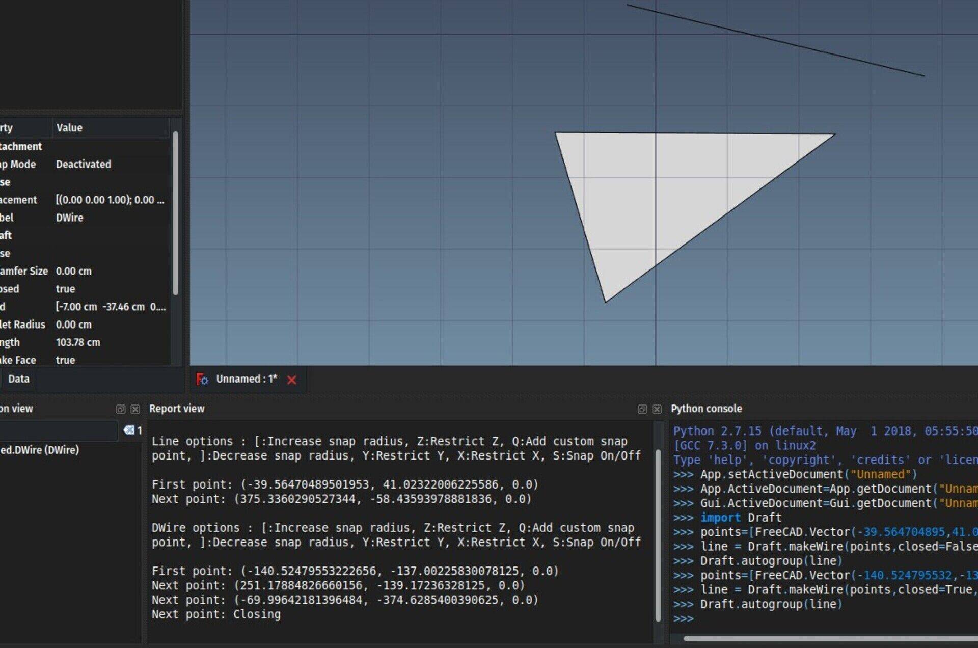
This is only an experiment so far.
It is a recurrent request from new FreeCAD users coming from AutoCAD: They want an AutoCAD command line. I don't like the idea, basically because it conflicts with a shortcut-based UI like FreeCAD has. If you look at how other apps with both shortcut-based UIs and command line do, for example QCAD or LibreCAD, it doesn't work really well. At some point the app needs to decide if the L key you pressed is a shortcut or the first letter of a command line command. You need either to move your mouse over the command window, or press SPACE to "switch" to command-line mode, which kills a bit the efficiency of it all.
But I have this idea that it would be possible to "fake" the system, and offer the user not a "real" command-line system, but a keyboard-only workflow with the same speed and easiness of the famous AutoCAD command line. To make it simple, pressing the keys would still trigger shortcuts and UI actions, but you would get a "feedback" of it in the output window of FreeCAD, making it look exactly as if you were typing stuff in it.
So far two Draft tools have been adapted to that system, as a proof of concept: Line and Wire. There are a couple of improvements to bring to the console, like the possibility to show stuff in bold font, or maybe enable clickable links, I will look at that later on. But I am not convinced yet if this is usful at all. After all, it is totally possible to pilot most of Draft and Arch commands via keyboard only since a long time...
Please test and give your opinion! There is a forum thread dedicated to this topic.
Material layer presets
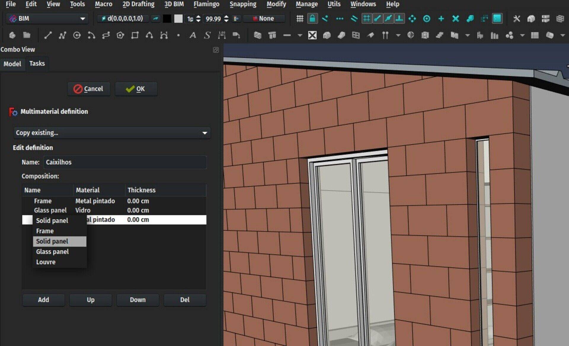
The Multimaterial dialog already allowed you to define different material layers, to be used by walls, panels, and windows. In the case of windows, it was a bit clumsy to use, you had to create one material layer for each window component. So if you had 20 panels in a window, you needed 20 material layers too. And take care that it uses the same name.
Now instead of a layer name in the Multimaterial editor, you can also click the drop-down arrow and select a window component type. That material layer will then apply to all window components of that type. So you now just need to create a Multimaterial with one material as "Frame" and another as "Glass panel", apply it to all your windows, and you are done.
BIM Views manager
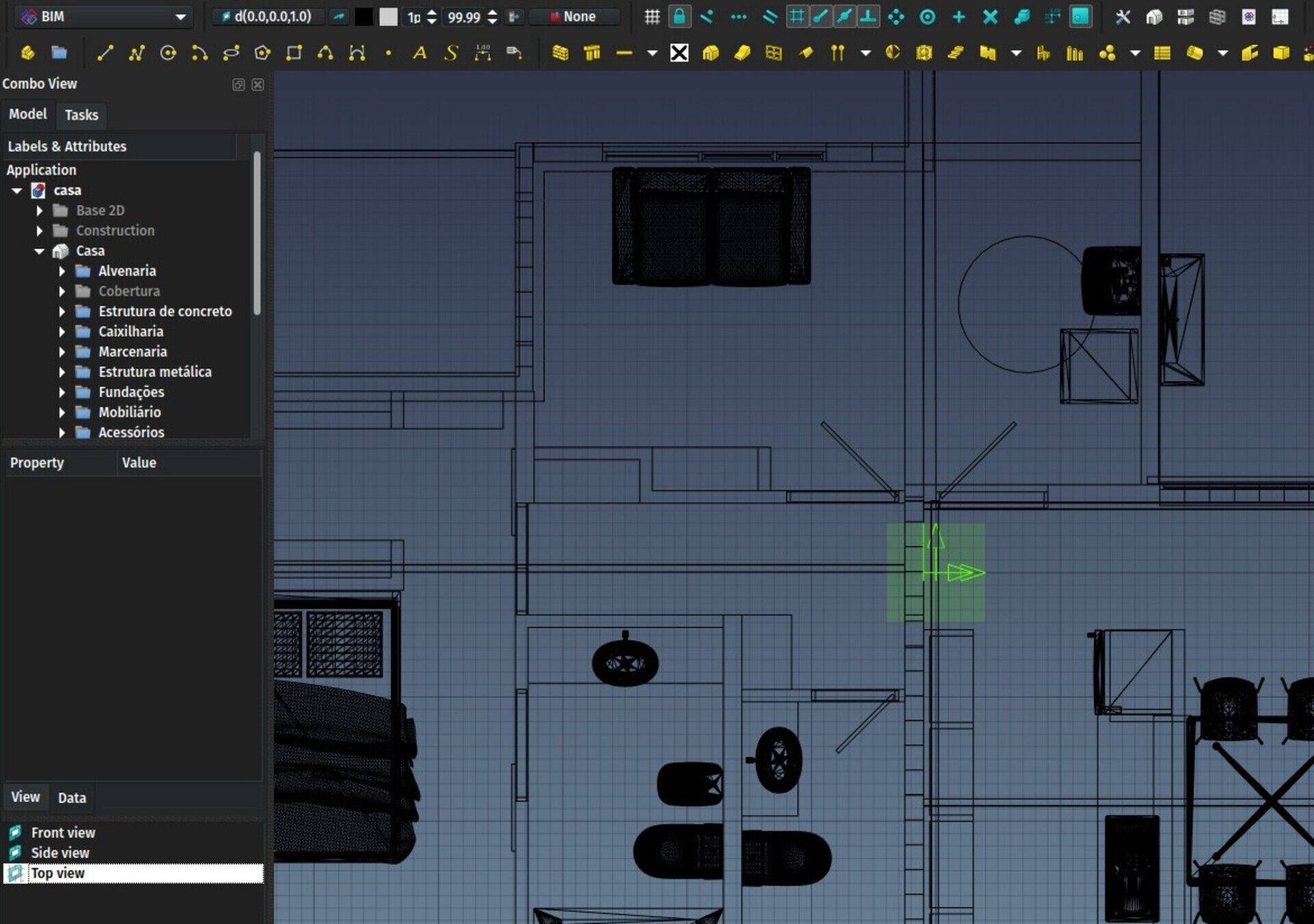
Another new widget is available in the BIM workbench: A Views manager, that will open inside your Combo View. It is basically a small widow that will list all the Draft WorkingPlane Proxies of your document. You often need to double-click them to set the corresponding view, but they are often buried deep down your model tree. Now they can always be conveniently be available there, no more endless scrolling!
Later on, as the BuildingPart object evolves and can also define a view, it will also appear in that view.
TechDraw DXF export
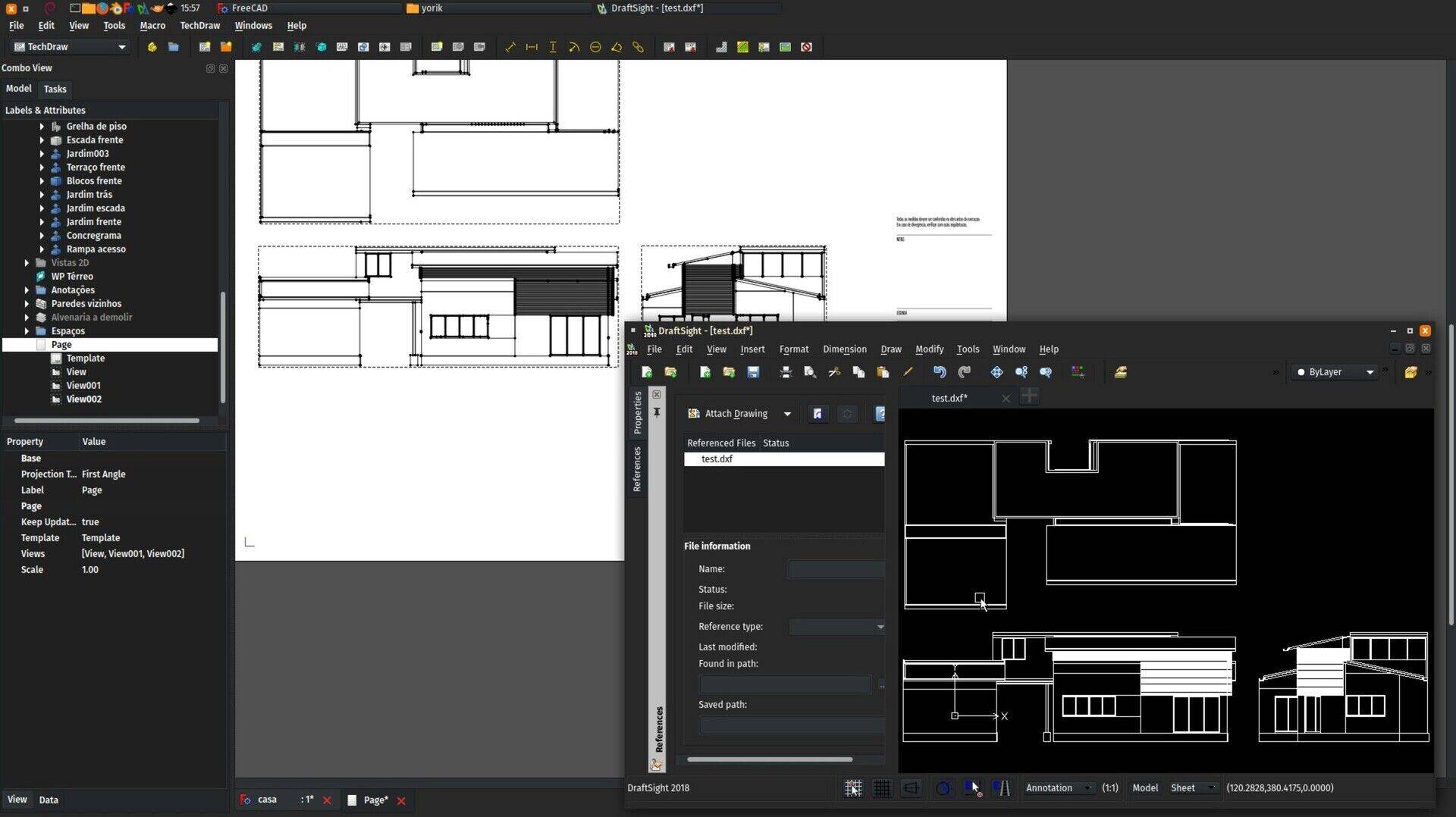
Finally, this is not mine but the result of the hard work of Wandererfan, the TechDraw master, and of huge importance to Arch/BIM users, TechDraw pages can now be exported to DXF. Every single TechDraw feature is not 100% supported yet, but Wandererfan is working amazingly fast on this, and it is very usable already. The result is a very clean and compact DXF file.
If you haven't tried to use TechDraw for Arch/BIM work yet, give it a try, it is still a bit slow for production use, but most of the needed features are there already, no doubt we are getting very close!
That's it for this month, thanks for reading, thanks for the support, more to come next month, don't forget, if you are new to these pages, I can go faster with your support!
This blog is not a good place to discuss all these items at once, if you would post this on https://forum.freecadweb.org I think the discussion can be much better and include other people as well.
But to give a short answer, if the IFC file contains IfcBuildingElementProxy objects, there is nothing we can do direcly, there is no way for FreeCAD to know it is in fact a window. But in FreeCAD itself any object can become any BIM object. So in this case you can take all the objects that compose your window, then Part -> Make Compound, then use the Window button to turn the compound into a window. This window will be unable to cut into a wall, though, becuase it has no way to know what shape should be used to do that. So you would need to model that subtractive shape yourself, and use it as the SubVolume property of your window. Another solution is, as you did, model the opening separately fromthe window.
FreeCAD does not have a parametric 3 pane window type. I had already drawn this window in Sketchup, so I went to my component bin and imported the 10’ 3 pane window.ifc into FreeCAD, and I was able to precisely insert it into a pre-cut opening.
It imported as a group of BuildingElementProxies instead of as a window. (This is pretty much what Solibri reported as well.)
I renamed the group and the elements and reset their colour and transparency. I set the material for the frame to wood. There is not yet a glass material to specify.
I was not able to make it into a window which FreeCAD could recognize as such. The clone of the imported 10’ window which I inserted into the wall came in as a single entity and I could no longer edit it’s components or derive quantities from them.
I inserted an 8’ version of Yorik’s new 4 pane window in the wall, I had no luck setting a material for the 4 pane window, or editing the components. (I want to be able to derive quantities (especially mass) for all the materials in the model. This procedure worked well when I did a quantity survey on a simple reinforced concrete beam.)


FreeCAD BIM development news - April 2018
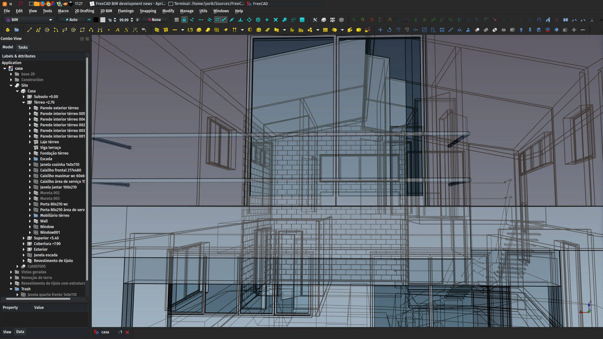
Hello everybody,
This is time for a new report on FreeCAD development, particularly the development of BIM tools. To resume the affair for who is new to this column, I recently started to "divide" the development of BIM tools in FreeCAD between the original Arch, which is included in FreeCAD itself, and the new BIM workbench, which is a plug-in, and is now easily installable right from within FreeCAD, under menu Tools -> Addons manager. The idea is to keep the "technical" side inside the Arch module of FreeCAD, and concentrate, in the BIM workbench, on workflow and interface. This makes it clearer for me, allows for more experimentation without touching the "core" stuff (and therefore keep existing users happy), and also makes it easier for other people to contribute, since there is much less code to deal with in the BIM workbench, and you don't need to know much about FreeCAD internals, nor need to compile anything.
As you certainly know already, this month we released version 0.,17 of FreeCAD, I wrote about it in another article. This was a long-awaited one, and a lot of things were kept back to make sure we fixed as many bugs as possible and delivered a reasonably clean and stable version. Now that this is done, experimentation and new features can start again!
As always, all this is possible because many of you are sponsoring me on Patreon or Liberapay so I can steadily and increasingly spend some working hours on FreeCAD every month. Thanks once again for the wonderful support, together we're firmly on the way to a fully functional and professional-grade open-source BIM tool. I sincerely believe there is not much missing. If you would like to help me, head to one of the two crowdfunding platform, any help is welcome! Also, we now have a Bountysource account for the FreeCAD project (not just me), although at the moment the money received has not been used for anything yet.
Video
So this month's video will be about generic Arch/BIM objects, and how to get started with BIM modelling.
Wall blocks
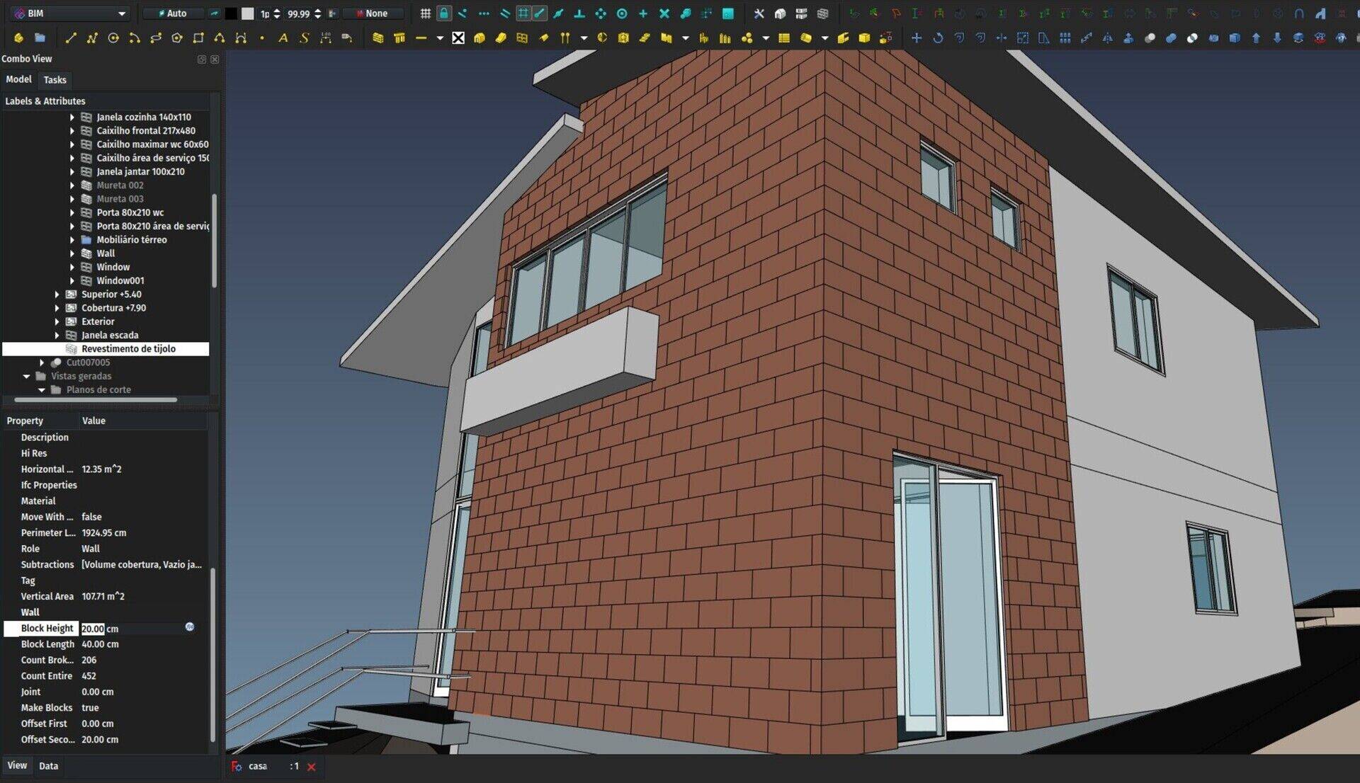
One feature I had been working on before the release already, that was ready and just waiting to be merged is a wall blocks feature. Now, walls can be made to display as blocks instead of the normal, solid wall. You can specify the size of each block, the size of the joints, and an offset for the first and second rows. In blocks mode, the wall will also calculate how many entire and how many broken blocks it contains.
So far this works only for walls based on a single line or on a wire. In case of wires, it can give wrong situations at corners, like blocks not properly cut like in real life. Walls based on faces or on solids cannot display blocks yet. Subtractions are supported, but additions not. This all will be addressed in due time.
At least for simple wall cases, you can now do pretty accurate wall design based on concrete blocks or brick size, check interferences, easily get the number of blocks, etc. This is only a start of course, but I think it will allow well to see if this goes in the right direction or not.
UPDATE WIKI
BuildingPart
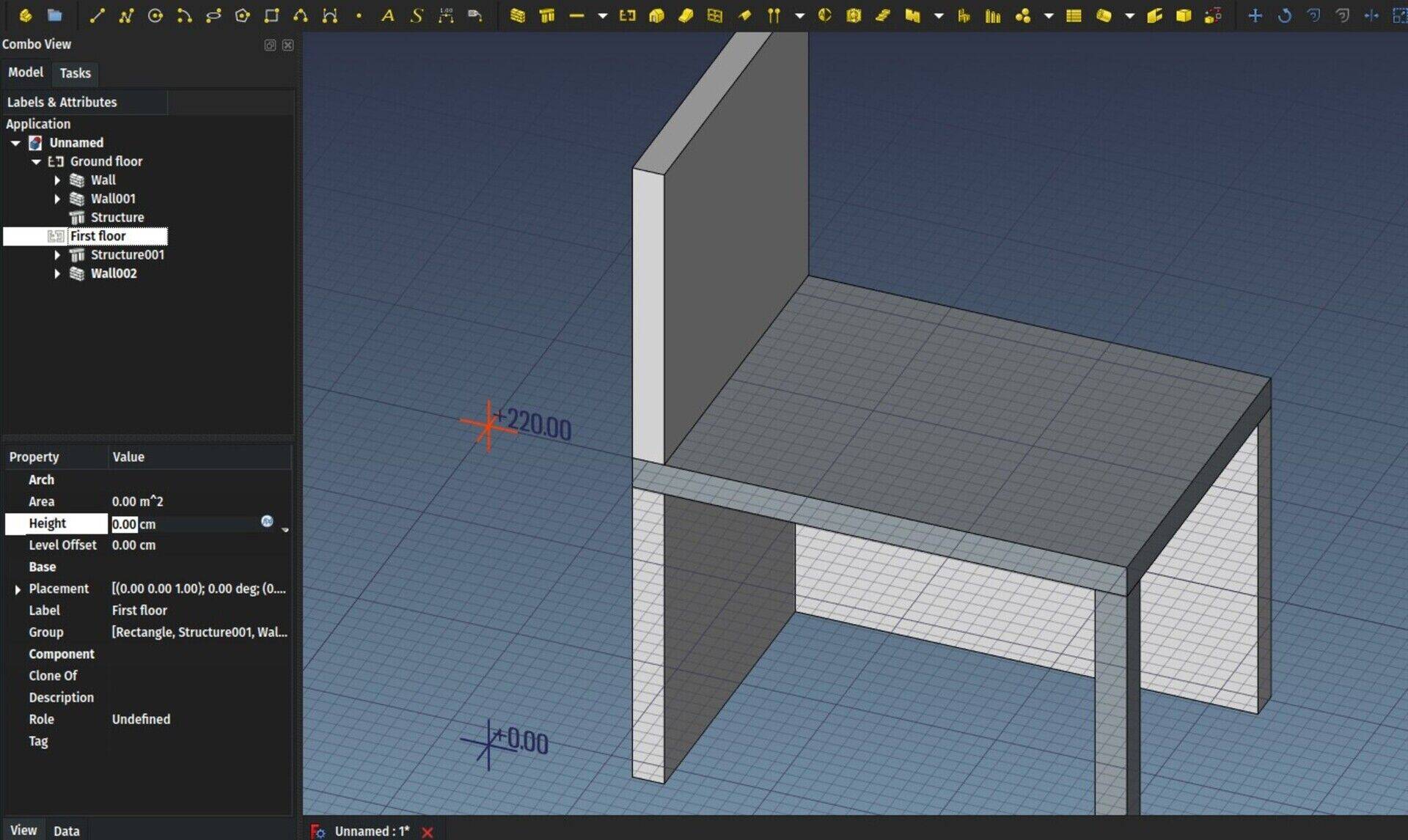
What I spent most of this month working on is unfortunately half a failure. But we shouldn't consider failures as less important than successes, they teach us a lot and are fundamental to get it right next time. Besides, as we are not totally stupid, we made things such as we can still reuse most of the stuff developed, so it is only a partial failure 
Basically my idea was:
1) to make the Arch Floor object a bit more generic, allowing you to group BIM objects in different ways than just stacking building storeys. For example a lift, which traverses a whole building vertically, cannot be inside one particular storey. Or you must cut it in little pieces, which is illogical. Resuming, we need less restrictive ways to group building objects. There was also a discussion about what name such an object should have, right now my favorite is BuildingPart, as it says pretty clearly what that object is, and is semantically in sync with the general FreeCAD naming of things, specially given point 2 below.
2) Instead of being just a group, I wanted to make this new object based on the new App Part feature of FreeCAD, which is the base used in the PartDesign Body. The main advantage is that it is a mix between a group and a shape. It has a placement, that defines a "local coordinate system". The objects that you place inside such an object have their coordinates not anymore defined relative to the global (0,0,0) point, but to the placement of their host Part. So you can move and manipulate a Part like if it was a single object. This looked (and still looks) perfect for our BuildingPart. This also links to another idea we raised with Ryan some time ago, that we should be able to design buildings much more based on components, and that component should be treated like any other BIM object (or family in revitspeak), you should be able to make other objects based on it, etc. And it should be whatever you need it to be: A shipping container, a restroom stall, a lift machine, etc...
So far so good, The main problem is basically that the App Part is too restrictive, it doesn't allow a same object to be in several Parts, and doesn't allow cross-Part links, both things that are used pretty often in BIM models. So in the next month I'm going to look at how to solve that, probably by "forking" the App Part (which is fortunately an extension now, so in theory it shouldn't be hard) into a less restrictive version that we can use in our case.
But all the other stuff I developed for the BuildingPart object is still there (you can test it by using this branch or looking at this commit and will be easy to adapt to any solution we come up with, so this is not lost work.
Basically, the BuildingPart can show an "origin" mark, so you know where its (0,0,0) or "insertion" or "pivot" point is, it can display a level mark, it can be a clone of another BuildingPart, it can act as a floor/storey, or as a gathering of Arch Spaces, in which case it will compute areas (and later on other properties of spaces) and of course it has a Height property that can automatically set the heights of included walls and structures. Within the ArchFloor module there is also a python function to easily convert existing Floor objects to BuildingParts.
Other ideas I have planned is to make it behave as a WorkingPlane Proxy, so you can double-click it and automatically set the view and working plane and display of other BuildingParts according to it, and also make it automatically create a view in TechDraw, not sure yet if by creating an Arch SectionPlane automatically, or maybe try to using TechDraw views directly (and therefore stop relying on the ArchView), which is something else I want to experiment with anyway.
I think that will give us a pretty cool tool to work with, I dare to say better than many commercial counterparts  I wished I had it ready this month, but it shouldn't take long.
Trash
Deleting things forever is something we don't want to do with our computer files, why do we need to do it in CAD/BIM apps? So now, in the BIM workbench, besides the standard "Delete" option, we also have a "Move to Trash" option, which will simply move selected objects to a "Trash" group (that will be created if not existing, you can rename and move if you want) and turn them off. There is no "Restore" option, I don't think that would be very practical because it might not be able to recreate the original links without destroying something, so I thought it safer to just let the user restore objects manually if needed, for now.
Anyway, since I implemented it, I find myself using it all the time (you never know if you won't need that window again later on), I'm curious to hear about you.
4-pane window
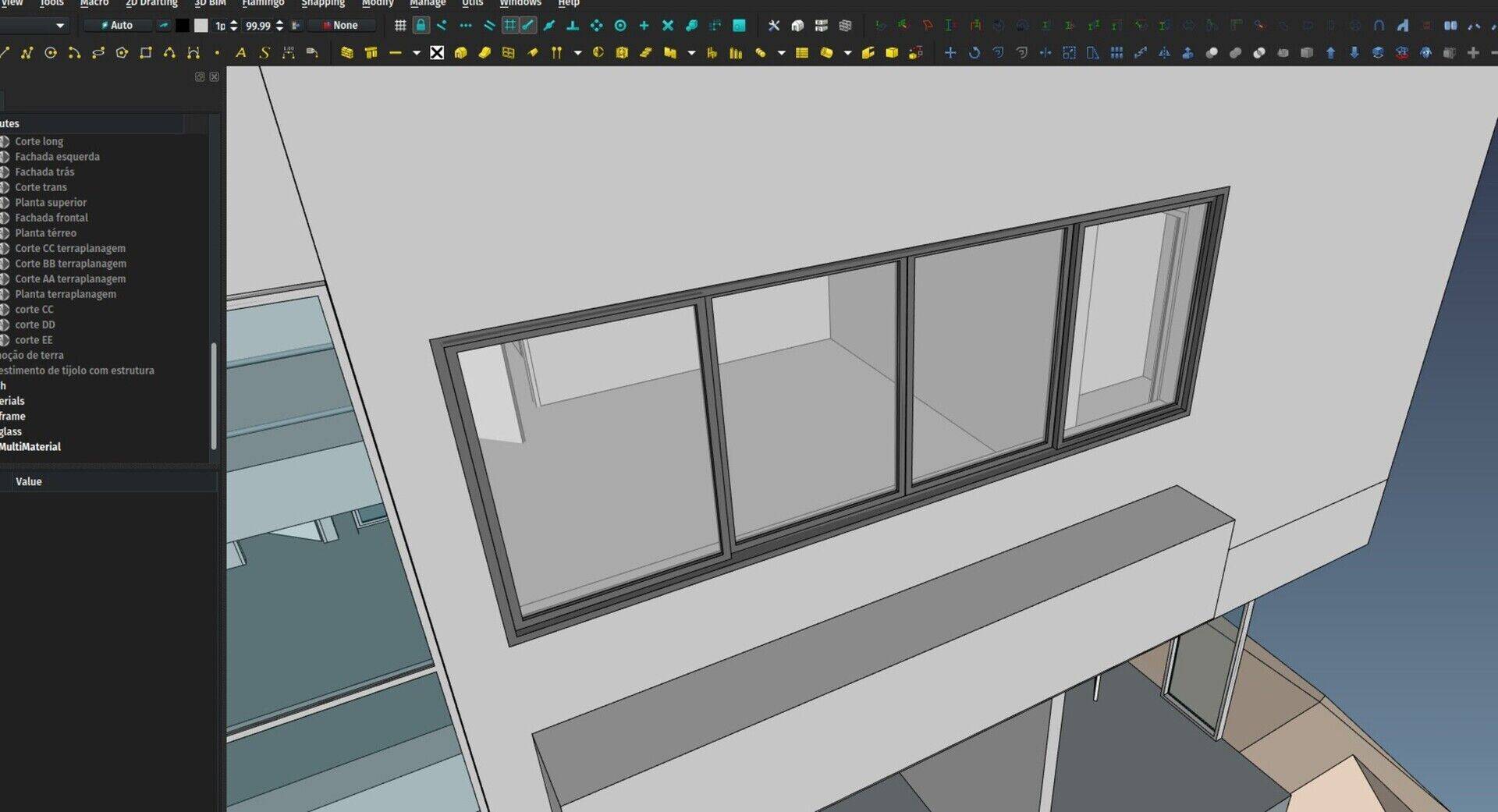
I added a new Window type too, which is a simple 4-pane sliding window. We use these a lot here in Brazil. I think we should add more prest types here... Remembering, of course, that the idea is not to have all possible window types listed here (that's the job of the library, see below), but let's say very common, or "archetype" window types. Any suggestion?
Library integration
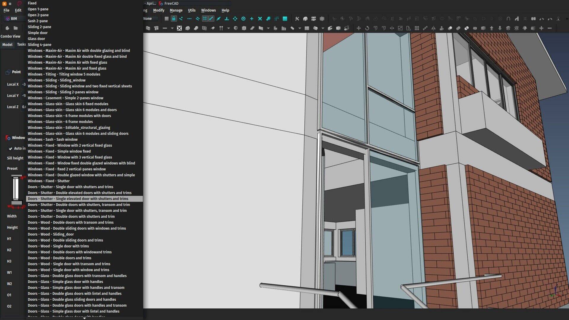
If you have the Parts Library installed (easy to install via the addons manager), then window tool will now include all the doors and windows found in the library (inside Architectural Parts/Doors and Architectural Parts/Windows). You might find that some of these library objects don't respect all the conventions, for example their width doesn't update correctly, but these are easy fixes that we must add to the library objects at some point. The fact is, it becomes easier than ever to add new window and door presets, without a single line of code.
GSOC
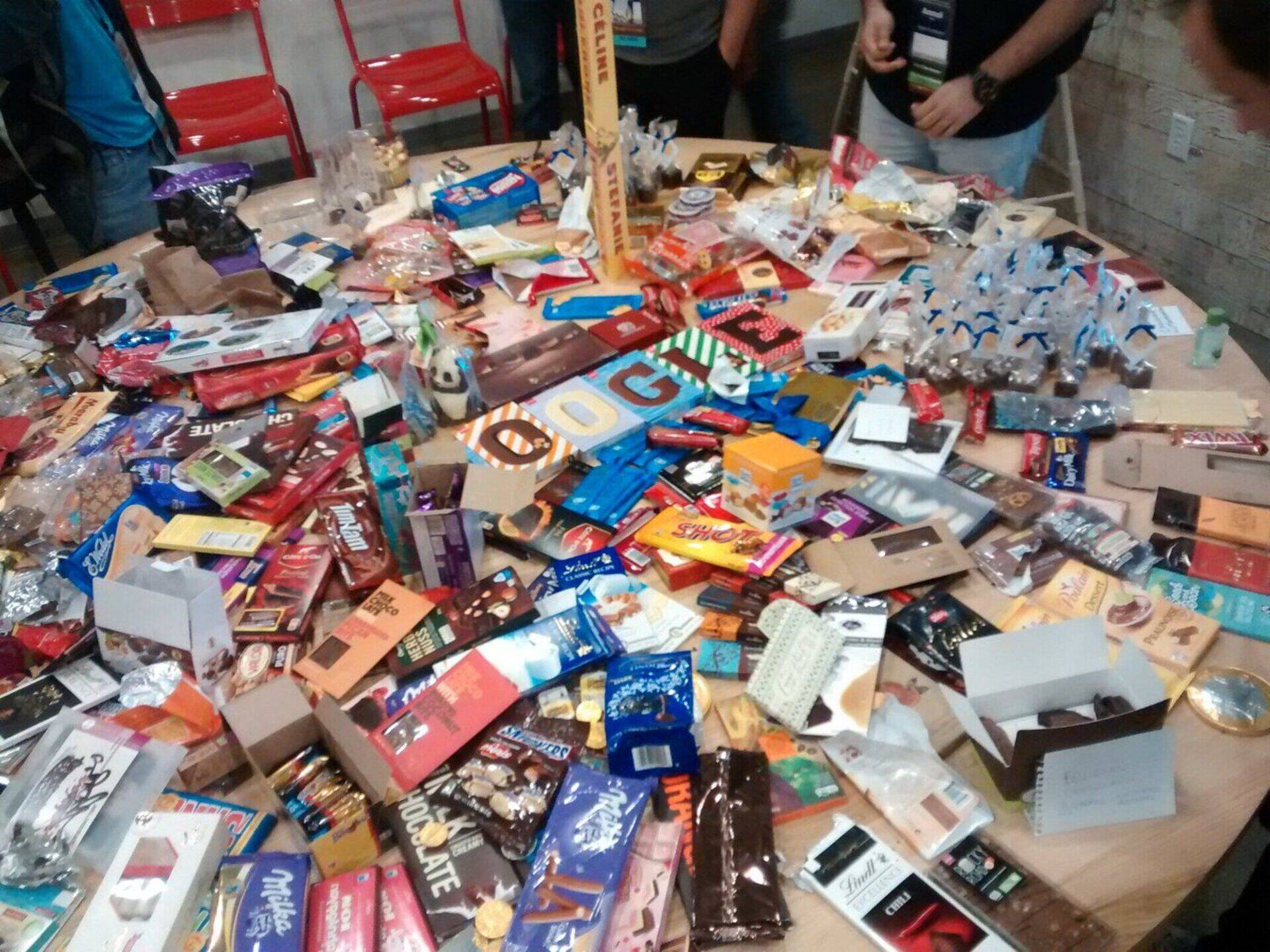
This year, like the last two years, FreeCAD will be part of the Google Summer of Code program, together with our other open-source CAD frends BRL-CAD (who are the brain behind the whole affair), LibreCAD, StepCODE, OpenSCAD, LinuxCNC and Slic3r. This year, we have one one student, Kurt, who is a well-known community member and already participated last year. His project this year is about implementing and bettering configuration and packaging management in FreeCAD. This is a rather generic project, but that is a good thing because it is also flexible and adaptable, and can make a big difference in the way we manage to make releases, which, you will certainly agree, will be highly welcome.
When the coding period starts, Kurt's project will mostly "happen" on the forum, which is now the standard way we do GSOC projects at FreeCAD. I'll announce it here too, so stay tuned to watch him closely! As he is the only student, all eyes will be on him!
In case you are wondering like me, all our other CAD friends also had few students this year, and generally many other projects too. Maybe anything changed at Google? In any case, let's not depend too much on Google, and be happy with whatever they want to sponsor. I'm sure we'll have a great GSOC experience this year again.
In case you are wondering, the above image is the world-famous Google Summer Of Code Chocolate Table, that gets set up during the mentors meeting, of which I have been lucky to participate last year. Every participant must bring chocolate from her/his country, they all go on that table, and you can eat as much as you want of it during the week-end. Believe me, even with the best efforts, we were hardly able to eat half of it...
Women in FreeCAD
Last weekend I was giving a FreeCAD workshop at the FLISOL, and, although women's part increases in such events (more or less one third of participants and speakers were women, my own estimation) I read some tweets afterwards complaining about some gender discrimination and argueing. This reminded me that we're doing pretty bad at FreeCAD, all developers are men, sometimes a woman appears on the forum, and, although I don't think there were any gender discrimination, for some reason none of them stayed until now. I would very much like that to change, I'm not sure how yet but I'll try to come up with ideas... If you are a woman and know (or would learn) some python and would like to get into FreeCAD, please, we need you!


Grazie, Yorik!
FreeCAD 0.17 is released
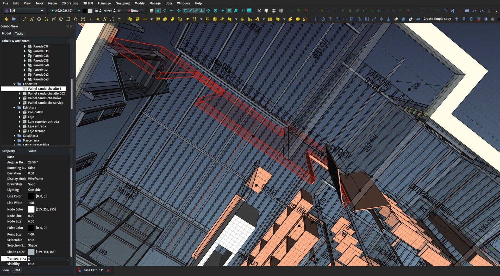
Hello everybody,
Finally, after two years of intense work, the FreeCAD community is happy and proud to announce the release 0.17 of FreeCAD. You can grab it at the usual places, either via the Downloads page or directly via the github release page. There are installers for Windows and Mac, and an AppImage for Linux. Our Ubuntu Stable PPA is also updated with the new version.
The list of changes and new features is big. Check the Release notes for a full dose. I will resume things a bit here, and, for once, I won't talk about BIM or Arch but about other workbenches. There is also a video showing the main highlights on the forum.
PartDesign
Basically the most fundamental change, and also the main reason why this release took so long to come, is that the PartDesign workbench has been drastically reworked, in preparation for upcoming Assembly system. As FreeCAD's father Jürgen once explained, the PartDesign workbench suffered from several flaws that prevented to implement Assemblies the way it needed to be. Several FreeCAD developers took upon themselves to dig into the already quite large PartDesign code and implement the necessary changes. This obviously caused a lot of new bugs, and it took a long time to bring it to a state where we feel it is suficently stable and solid for everybody to use.
The principal change is that now everything you do happens inside a Body. The Body is a hybrid between a container and a shape. It also contains many helpers such as planes or axes that you can use in different operations. The ultimate goal is that the body is what will allow for one FreeCAD file to be a part of an assembly in another file.
You might feel a bit lost when starting to use the new PartDesign, but fear not, after you pass through these new things, everything still works pretty much like before. And everybody who went through it agrees that it is much better than before.
Path
The Path workbench also got wildly extended. From its embrionary state in FreeCAD 0.16, it has now evolved into an increasingly impressive CAM platform. Yo have now a wide range of tools to perform CNC operations, several filling algorithms to fill areas, fin-tuning and gcode inspection tools and a voxel-based simulation tool like in your favorite commercial CAM software.
There is a long path to be done for Path yet, sorry about the bad joke, but it is no more an infant, it is now a real CAM tool, that can do the whole thing from the 3D model to the machining.
TechDraw
TechDraw is the new Drawing. It is another of these workbenches that has been carried successively by several developers, and on the way has gained impressive features. It still accepts the same templates as Drawing, has much finer control over aspect and linestyle than Drawing had, plus a load of new features: Most of the dimensionning tools of Drawing Dimensioning, hatching (both geometry-based and image-based), support of bitmap images, etc. But I kept the best for the end: The dimensions you add in TechDraw are parametric. You update the model, the TechDraw view updates too, and all the dimensions attached to it.
Addons
Finally, and not the least important, the number of new workbenches being developed outside of the FreeCAD official source code is growing frenetically and exponentially. FreeCAD 0.17 now features an easy Addon installer, that allows you to install any (or all, why not) of these juicy workbenches with a mouse click right from inside FreeCAD.
Go get it, it's free!

It is hard to give you an answer here, it's best to use the FreeCAD forum at http://forum.freecadweb.org and describe more precisely the steps you did, many other people will be able to help.
And design
I draw the table, the Lego exercise that works perfectly but with the draft bench it is impossible to work.
Could you help me ?
Many thanks
@Eric sure!
BTC: 35g6JrKKYBJjG7YXxpNcpjVCzNae6CmaNo
ETH: 0xF4e4756b1dAc0e637bAd7A4A528BaA3A44Ce1A92
URL written incorrectly: "comma" should be replaced with "dot"


FreeCAD BIM development news - March 2018
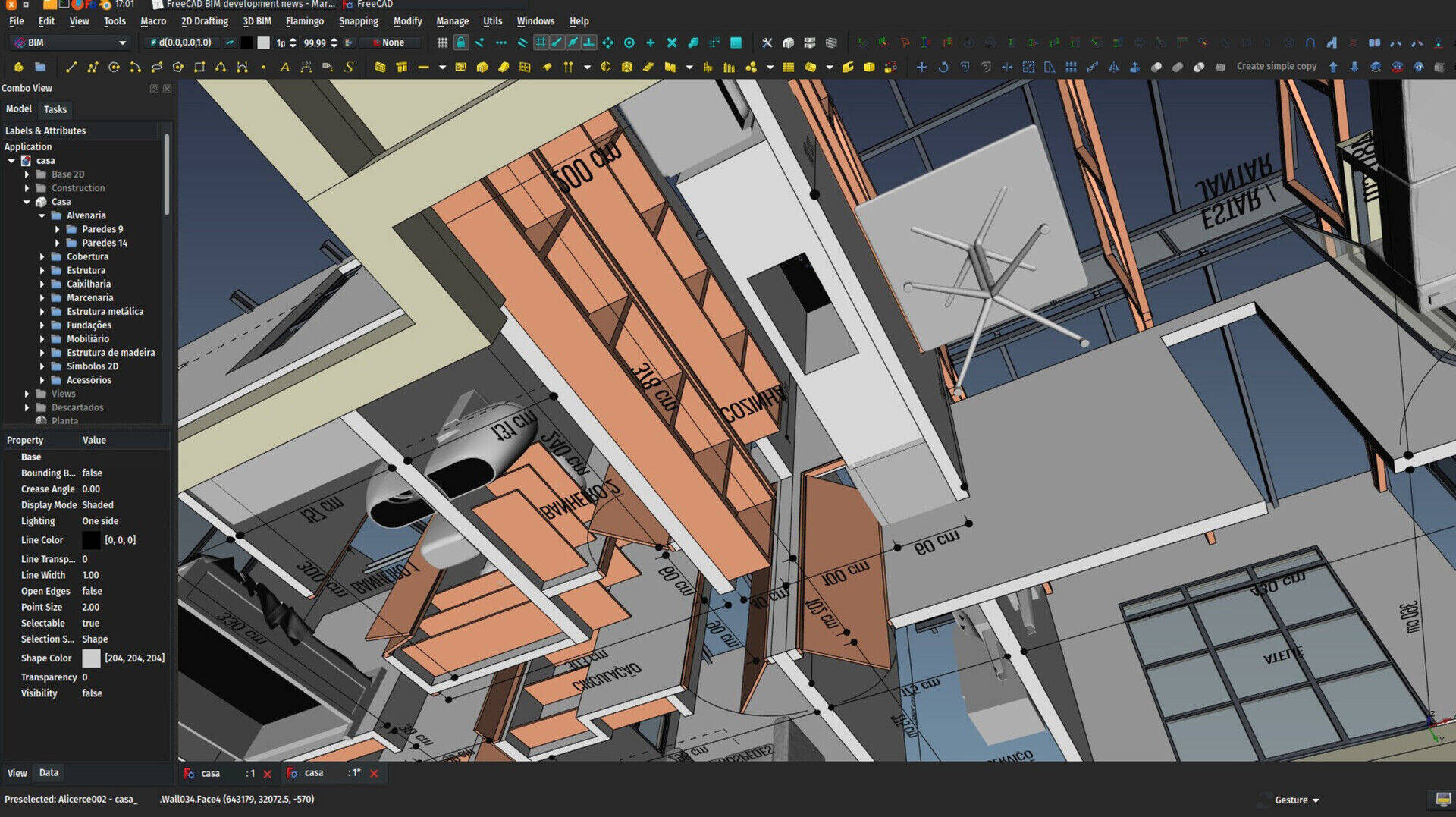
I hope you noticed the small improvement in the title... It's not that I became suddenly a big fan of the "BIM" term, but really the word "Arch" is too narrow in todays construction field. Besides, as I explained last month, I am now starting to split the BIM stuff in FreeCAD in two parts: One is the Arch workbench that you already know, that stays integrated to FreeCAD, and that will carry all the "dirty stuff" (objects, tools, base functionality), and the other is the new BIM workbench which will contain only UI elements (wizards, managers, etc). Starting from FreeCAD v0.17, installing the BIM workbench is very easy with the addon manager.
Talking about v0.17, the release is a bit late (we wanted to do it before end of February), but bugs kept coming in, and we are fixing them all! So it got a bit delayed, but we are finally there. In the coming days we should have it released. I'm adding he latest translations from crowdin as we speak. You can already check what's new in the 0.17 release notes.
As always, thanks to everybody who is contributing to my crowdfunding campaign on Patreon or Liberapay. I am now more and more able to regularly dedicate a good portion of working hours per week to FreeCAD, that I try to balance between developing new stuff, fixing bugs, and do all kinds of maintenance tasks. The main focus, of course, is still to push BIM development forward. As soon as the 0.17 release is out, I have already a few features that are ready to merge into the main FreeCAD source code. More on this next month!
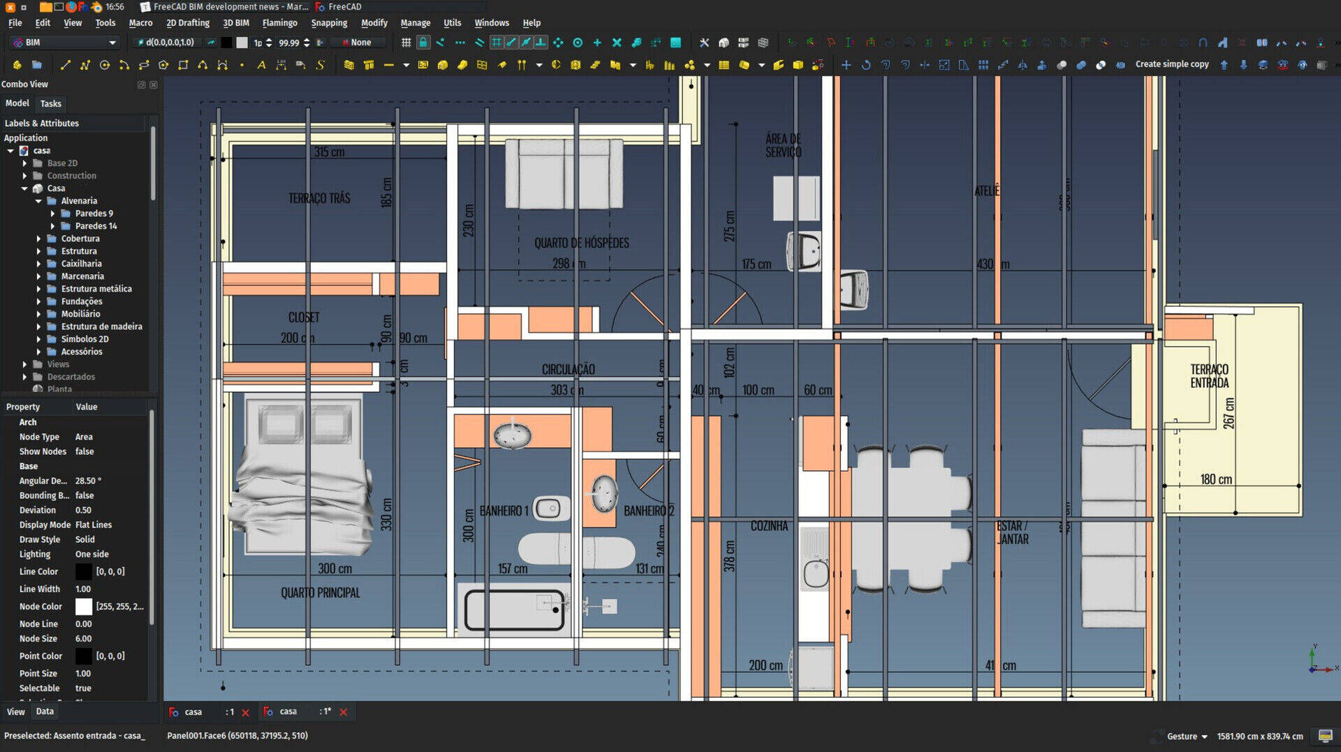
The video
Last month, I posted a first video introducing the Arch workbench. I made a new one this month, showing how to set things up and get started to do BIM with FreeCAD. Thanks for the many of you who left comments under the first video, this gives a lot of further ideas. Please keep going on!
One important thing I forgot to mention last time: There is no need to wait for me to make all these videos (Anyway, the idea is not to make a full course, rather toillustrate the concepts of how things work). There is already a lot of material on the internet, and specially the very impressive series of tutorials by Regis about FreeCAD and BIM, and other ways to do architecture and BIM work with free software like Blender. What you have there is a more than complete course of FreeCAD BIM, and for free... Amazing work Regis!
So, here is this month's video. Hope you'll like, please keep commenting!
The BIM workbench
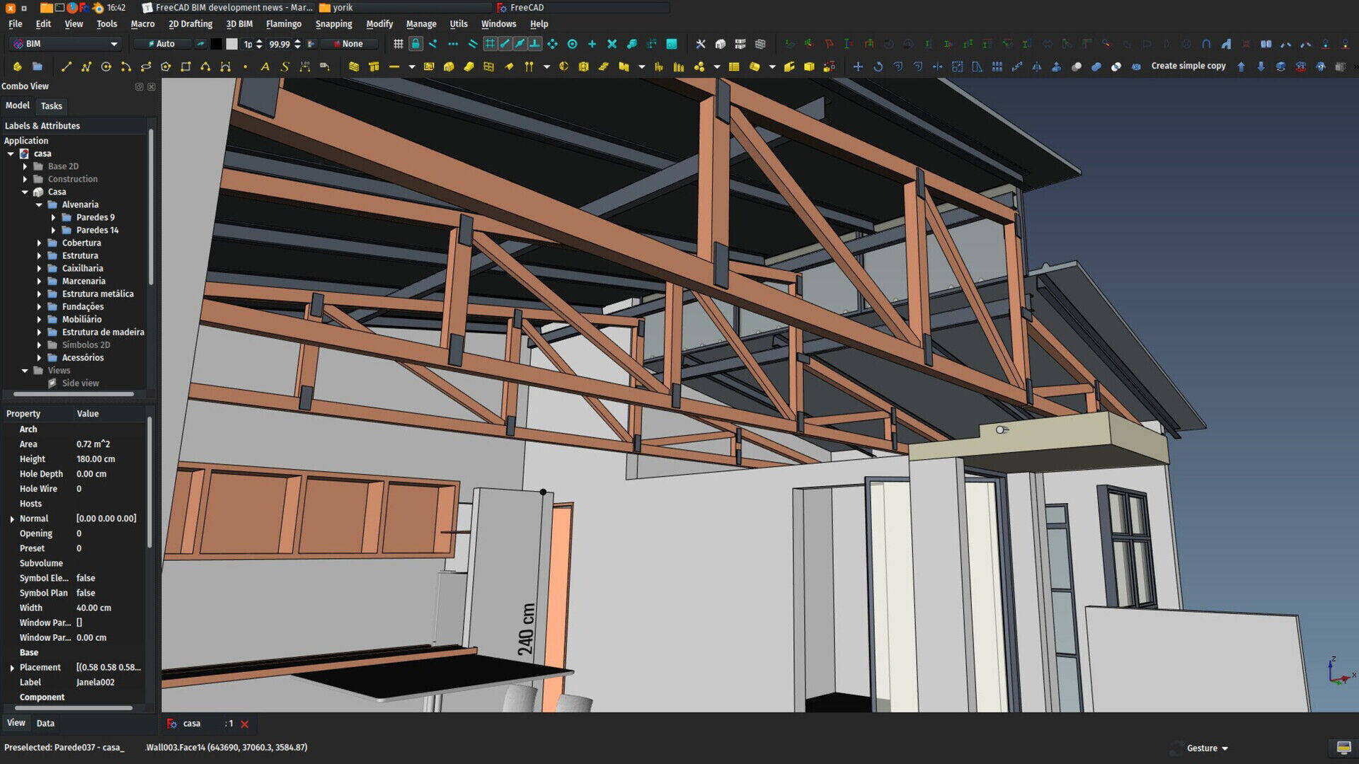
While FreeCAD was in "feature freeze" mode this month, the new BIM workbench, being developed outside of the main FreeCAD source code, allowed me to keep working on some cool features there. There is not much of a revolution there yet, but I believe this is going in the right direction. What we have so far is this (keep in mind that all this is experimental, it can change in the future):
A welcome screen
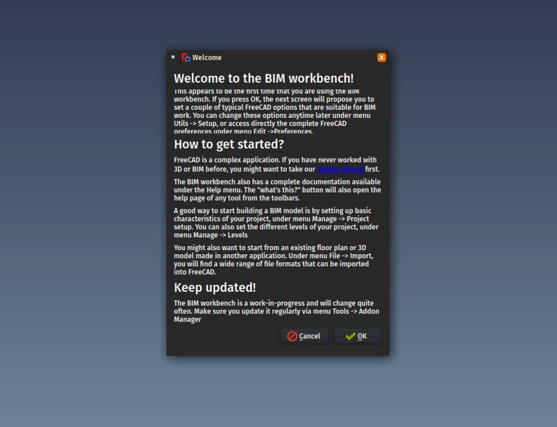
This screen is shown to you the first time that you switch to the BIM workbench. The idea is to tell you, in a few words, "what to do next", and offer you to follow a tutorial (yet to be written). You can still show that window again anytime from menu Help -> Show welcome screen. I must think a bit more about the tutorial but the idea is to do like in games, where when you take the tutorial, you are usually playing the first chapter of the game, but with an assistance that tells you what to do.
If you pess OK, you go to the next step, which is:
The setup screen
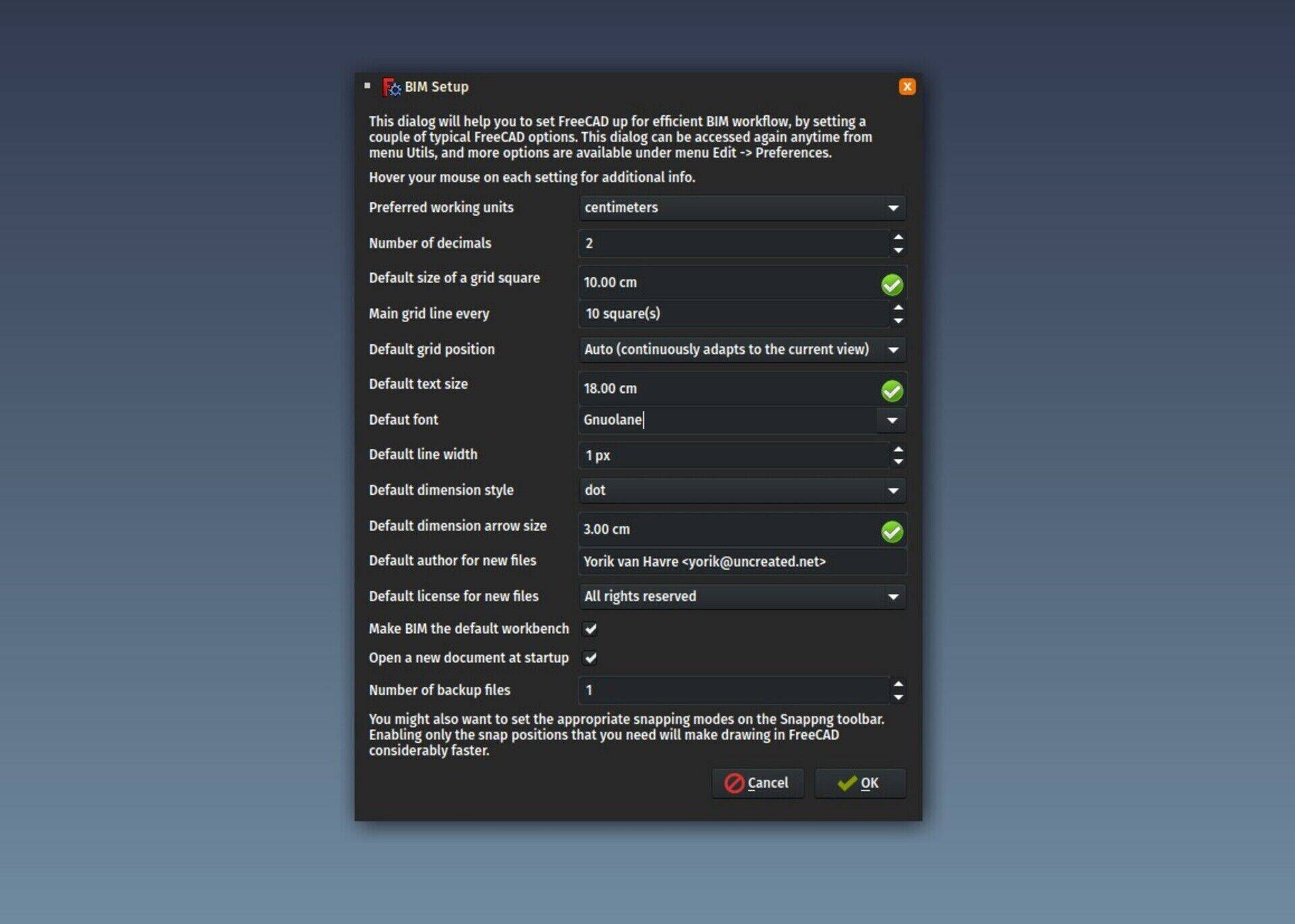
The Preferences system of FreeCAD is becoming huge and complex. And some preferences get loaded only when the corresponding workbench is loaded. It is very hard for a newcomer to find what options he/she needs to set. So we have here a summarized and unified set of the most important preferences for BIM. Some are grouped, for example when you set your preferred text font, it will set all the places in the preferences where a text font can be configured, for example in Draft, Arch and TechDraw.
Project setup
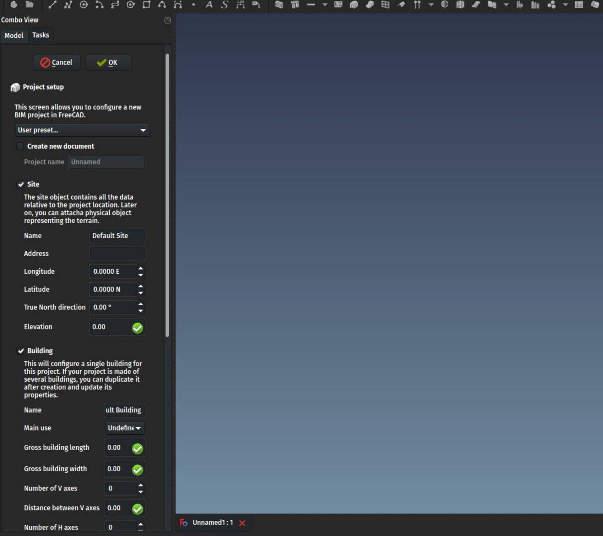
This is a new dialog that allows you to quickly setup a BIM project. It will optionally create a new document, create a Site, a Building and a couple of Axes, Levels (the Floor object in Arch will soon be renamed to something less ambiguous, my favorite at the moment is "Level", although I would like to find a word that doesn't necessarily suggests that things must stack on top of each other, maybe Zone, or Cell?) and a rectangular outline of the building.
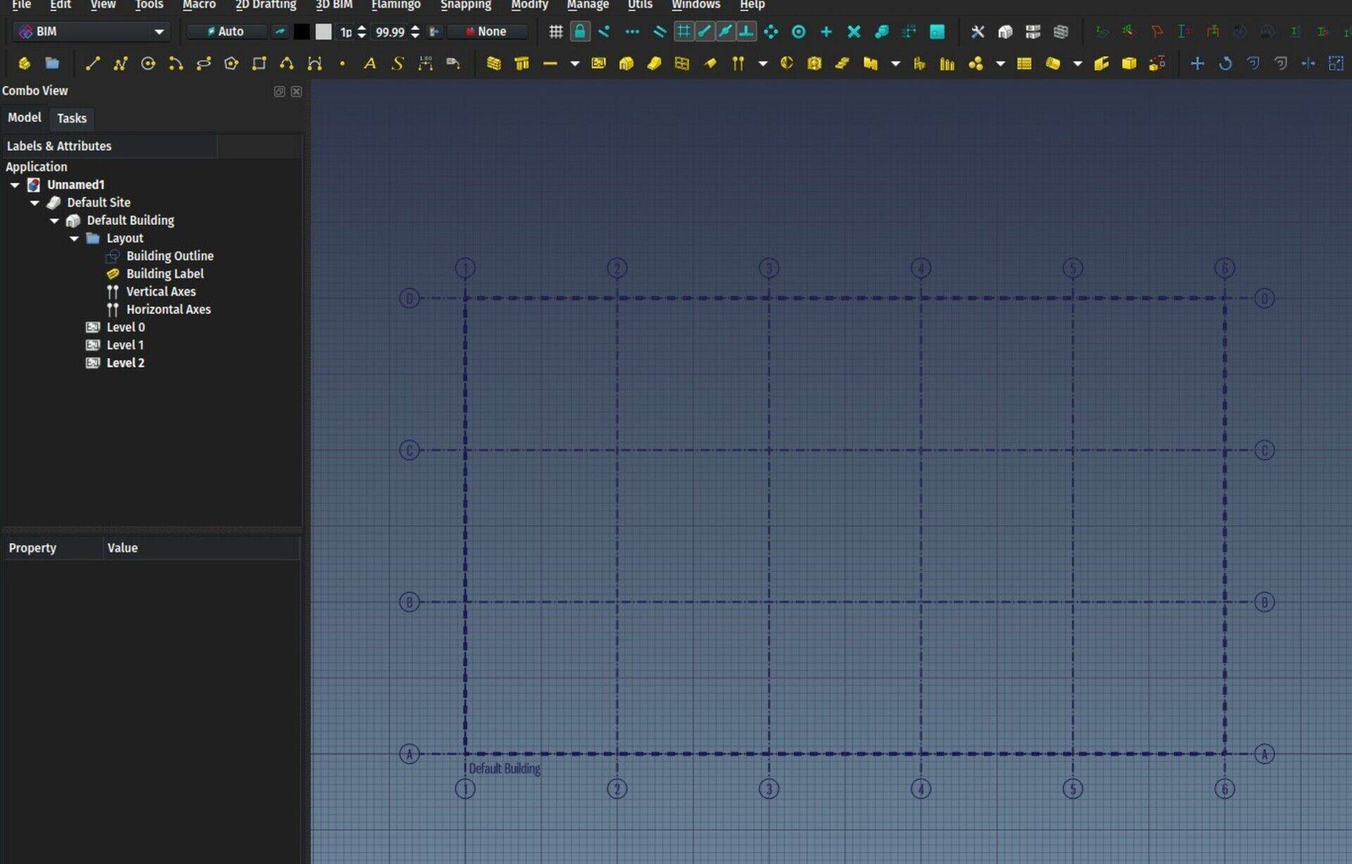
With that done, you have something to start building walls on. What you fill in that screen can be saved as a preset, so you can have several building templates around. The axes and outiline are linked, so moving the outline around will move the axes together, a good example of the powerful expression system of FreeCAD (check the Placement property of the axes).
Levels manager
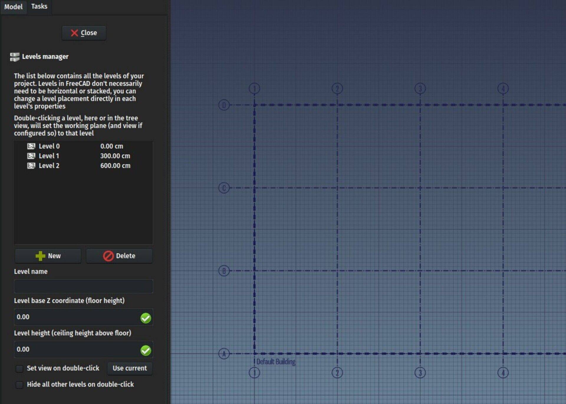
This is a simple interface to manage the different levels (Floors currently) of your document. At the moment you can only do basic things such as changing their properties and add or remove levels, but the intent here is to add more dependent functionality to levels, like WP proxies, which would allow neat things like, upon double-clicking a level, hide all other levels, and set you in a configured view (for example a top view above the level plan). This would mimmick quite well how other BIM apps work, where you can isolate a particular level to only work in it.
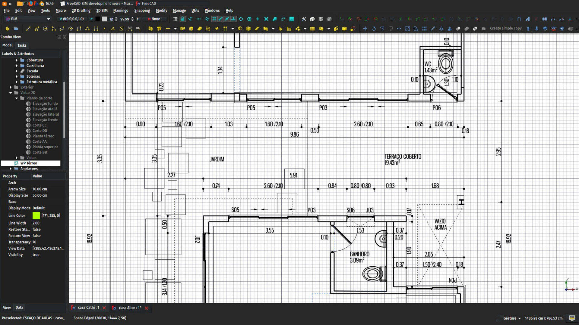
Another idea I have is to have a section plane automatically associated with a level, and make it (optionally of course) cut the view above it when you select the level
Windows manager
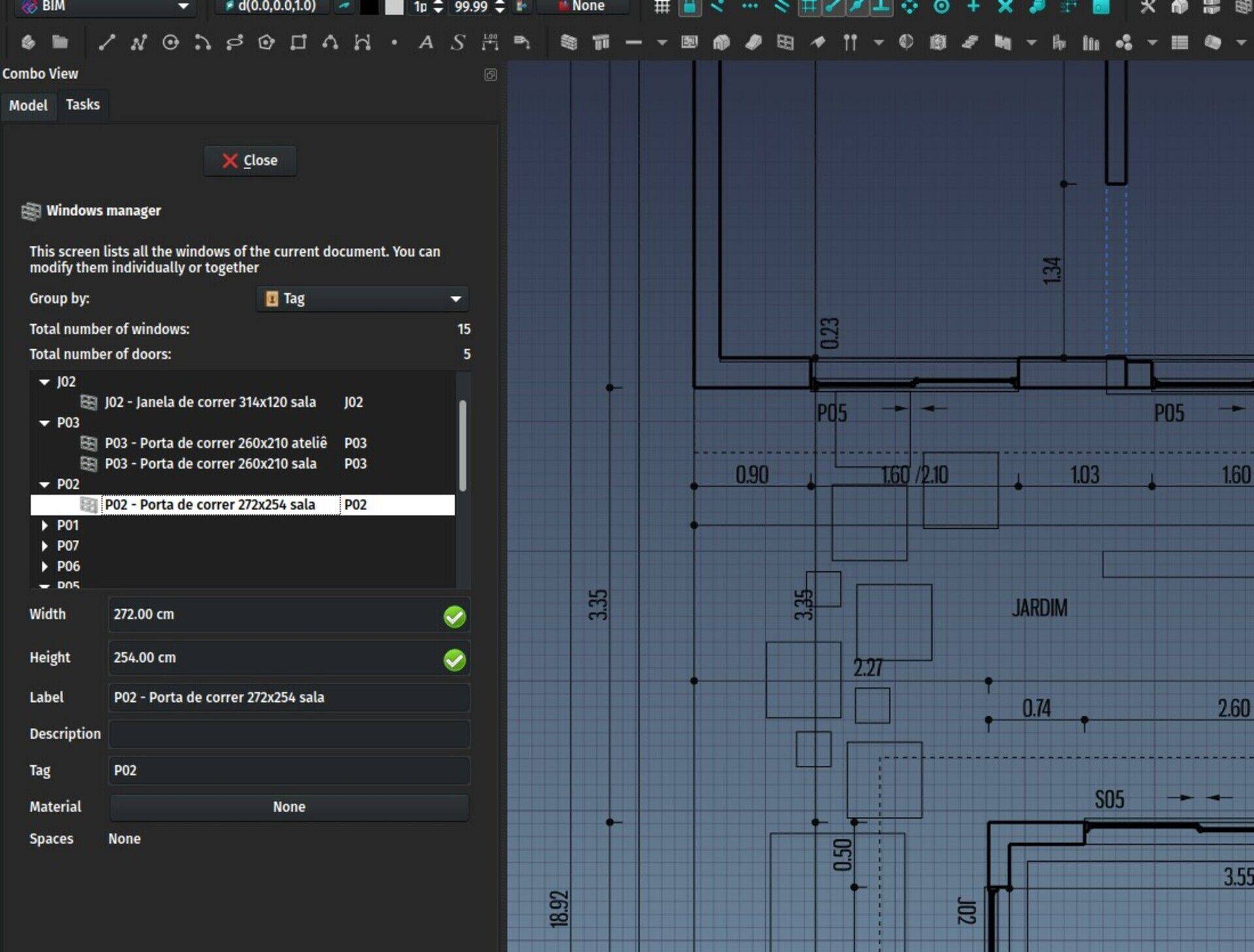
This is a simple screen that allows you to manage all the windows and doors of your project. So far it doesn't do much more than list all windows and doors, and allow to group them by type or dimensions. But the idea of this screen is basically just that, allow you to have a clear view of all the windows and doors, see what is missing or wrong, and in the future, or course, allow you to export this to a spreadsheet.
The BIM workbench source code
If all this thrills you, I would encourage you to help me. Of course an easy way is to contribute to my Patreon or Librepay accounts, but I would also encourage you to help in other forms. There is more in several heads than in a single one, my grandmother used to say...
We have a forum thread where you can contribute to the discussion, but working directly with the source code is not hard. In a next report I will explain better how it is organized, but you have basically, for each tool, an .ui file which is the design of the dialog, made with QtDesigner (which is part of the QtCreator suite), and a corresponding .py file that has the code that runs "behind" the .ui dialog (ie. what happens when you click such button, or click on such item, etc..)
QtCreator is a complex application, but the QtDesigner inside is very simple to use, it is very easy to constructs dialog boxes with it. And when designing User Interfaces, a great deal of effort goes into thinking and constructing intuitive dialogs. This effort is often bigger than writing the code behind. So playing with these dialgos and proposing ideas with it would be helping the project tremedously, even if the code is to be written by someone else later on.
But the python code behind these BIM dialogs is not too complex either, have a look 
Speckle
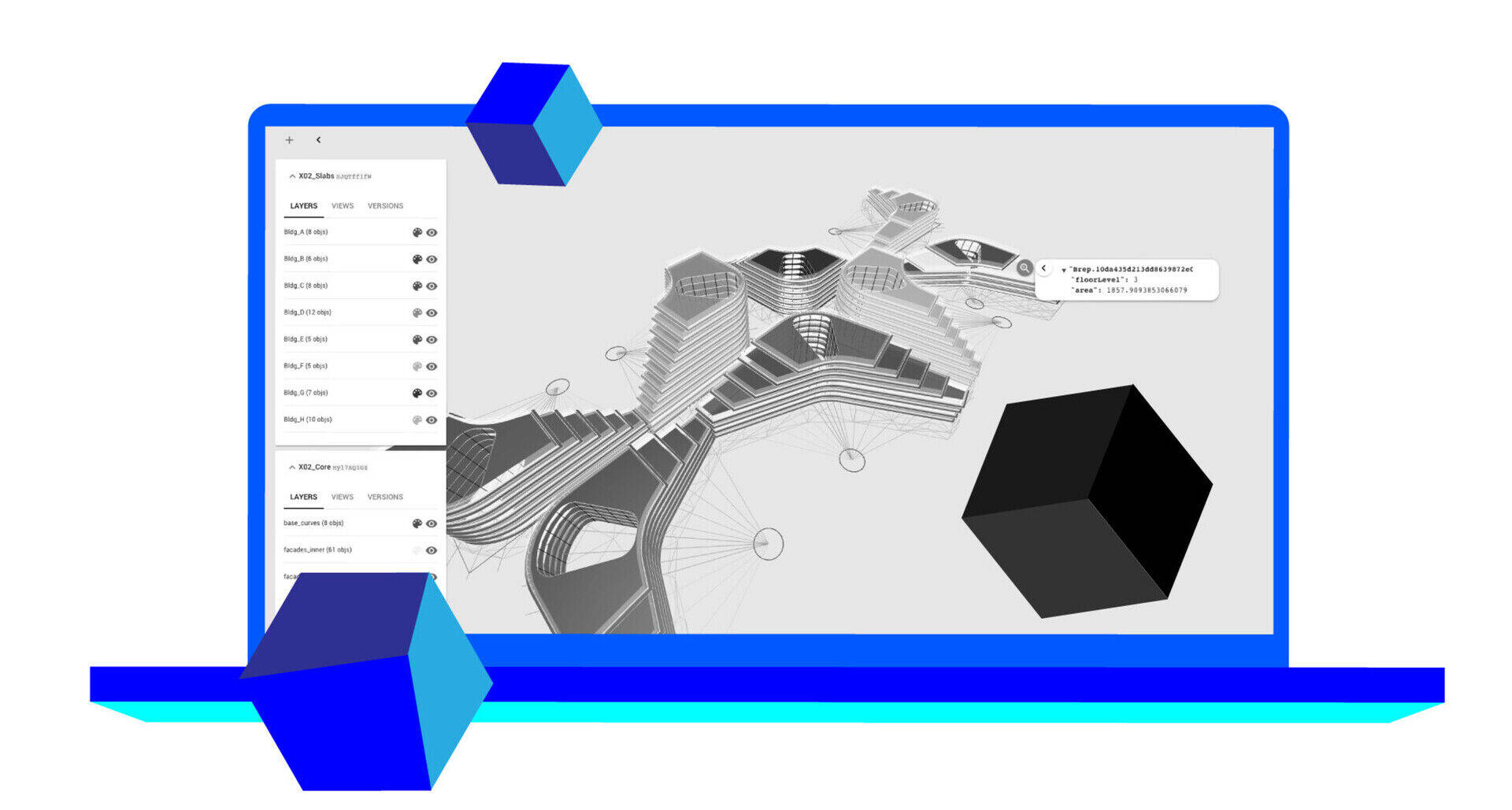
(image swallowed from the speckle.works blog)
Thanks to Ryan I discovered Speckle last month and got fascinated. It is a free & open-source 3D model server, a bit like BimServer, but, instead of being based on IFC, it is built for parametric 3D models. It is basically everything I wished BIMServer would be: It speaks json, a widely used transfer protocol, and it is totally system-agnostic. In it, you have collections of objects (streams), each object being a collection of properties, and that's it. The parametric "engine", that knows what to do with these, stays in the original application.
So for example, a cube would have a name, a text describing its type ("cube", for example), and length, width and height properties. That's all that would get stored on the Speckle server. But FreeCAD would know exactly what to do with such info. And so would Rhino, Blender and anything you would plug Speckle into. It is particularly well adapted to those so-called "visual programming" interface such as Grasshopper or Dynamo, of course, but a FreeCAD model could also be transferred to/from a Speckle model with almost 1:1 compatibility. This is something I experimented in IFC a while ago, that can be carried on here way further.
So I started working on a Speckle interface for FreeCAD (probably will be part of the WebTools workbench). I believe this can yield wild results...
That's it for this month, thanks again to everybody for your support, see you next month!


Ben nu al een hele tijd opzoek naar gratis of betaalbare software voor het 3D (mechanisch) tekenen aangezien ik nu toch al wat jaren enkel in 2D teken (Qcad) . Na toch heel wat zoekwerk en het vergelijken van verschillende software heb ik gekozen om binnenkort met Freecad aan de slag te gaan , dus kijk er wel enorm naar uit hier mee te starten! Nu wacht ik voorlopig nog op de release van de 0.17 versie . Doe zo verder zou ik zeggen en de groetjes uit Belgie !
Obrigado, estou feliz que ajudou. Não sei sobre 3D, na verdade nem percebi que o GeoSampa tinha... Vou dar uma olhada nisso. Suponho que um plugin desatualizado não seja algo muito grave, ou o autor vai atualizar logo, ou não deve ser muito difícil arrumar...
Descobri recentemente esses novos mapas do GEOsampa e vai me ajudar absurdamente no meu trabalho! Seu tutorial foi ótimo para me ajudar a abrir o .shp porém eu gostaria de abrir o mapa com as edificações em 3D e não consegui. Também tentei o plug in do Qgis que abre 3D mas não está disponível para a última versão 3.0 do Qgis. Alguma dica para me ajudar?!


In order to identify and try to define what that "ideal" BIM workflow would be, it might be interesting to express a series of goals to be achieved, for example:
- Be possible for someone who never did BIM before to learn more or less easily
- Be possible for someone used to other BIM software to learn more or less easily
- Be able to model simple houses
- Be able to model complex buildings with repetitive components
- Be able to produce nice-looking, complete and up-to-date 2D plans
- Be able to produce complete and up-to-date lists of quantities
- Be able to produce nice-looking images
- Be able to study the thermal behaviour of buildings
- Be able to produce buildings that are compliant to local thermal regulations
etc, etc... There would be some organizing to do there, subdivide this into subitems, etc. But it might be a good way to approach things.
This is great idea.
Two things came to my mind re above+FC
1. As per FC's BIM - full control over bill of materials and cost /fast changes recalculation for investor, contractor/
2. A goal to comply with coming EU thermo codes/regulations, thermal calulactions (maybe worth looking at /www.passivehouse.com /
FreeCAD Arch development news - February 2018
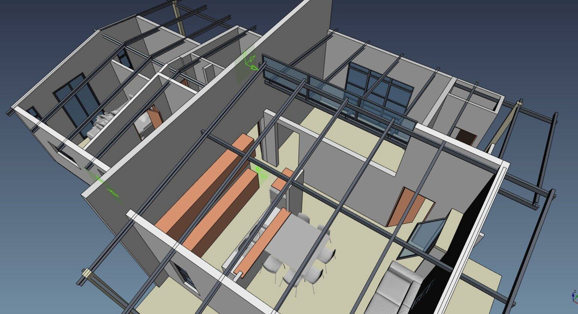
Hi all,
Time for our monthly development update. This month again, no new feature has landed in the FreeCAD codebase, because we are still in "feature freeze mode", which means no new feature (that might break something) can be added to the FreeCAD source code, only bug fixes.
We hoped to release version 0.17 in February, but, as usual, this has been delayed a bit. There are still some bugs remaining, and there is also some documentation missing. The whole community is working hard to fix this, so it won't take long and we will have a release with the documentation in a very good state, much better than it has ever been before.
Translations are also basically done, we have 16 languages over 90% translated and 5 100% done, which is more than we ever had in the past. It is still time to help us!
I have myself been busy touching all these areas, and also done more bugfixing in Arch and Draft. I think these two workbenches are getting pretty robust now, which is basically the level I wanted to reach at this point. My intention after the release is not to touch these features too much anymore, and concentrate on building better UI tools to manipulate them.
By the way, TechDraw is becoming more and more useful for BIM work, hopefully we will soon be able to retire the old section planes system for something much better... It is still a bit slow and not totally adapted to architecture/BIM (you must produce the elevation before the plan, for example), but those are all solvable issues. The results are very nice already...
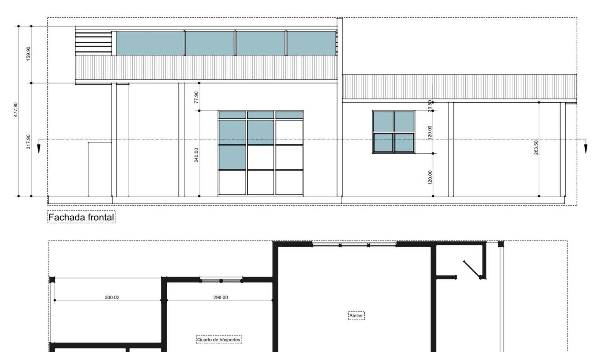
The video
As promised last month, I tried to record a video this time. Let me know what you think of it, sorry about the non-professional quality, I'm not a professional youtuber yet  I propose to do more later on, about specific parts of the Arch workbench.
Pionierswoning
Since I was in Europe last month to attend FOSDEM (read about it in my previous post, and the video of my talk is here), I also took the opportunity to visit the Pionierswoning (Pioneers housing), another WikiHouse-based construction that happened in the same time as the WikiLab (We even had a dummy "competition" to see who would finish first) and talk with Vincent and Ivar who are behind the project.
This was a very, very interesting visit. The Pionierswoning is part of a bigger experience in Almere, to build experimental tiny houses. The number of single-person houses is climbing strongly in the Netherlands, and this becomes a very real question to solve. On the same site as the Pionierswoning are 5 or 6 other tiny houses made for one person, all of them with different approaches and solutions, definitely a very interesting place to visit if you are in the area (it's only a 15 minutes train ride from Amsterdam).
The Pionierswoning itself is definitely a very interesting achievement. Contrarily to our WikiLab, where we tried to be didactical and keep the wooden construction as apparent as possible, the aim of the Pionierswoning was opposite, they try to show that it could make a house like any other. As a result, you don't see the WikiHouse structure anymore. Most solutions that they adopted as finishings, both inside and outside, follow the same direction. It is amazing to see two projects built basically on the same structure, give such different results.
And I must say, the finishings they did are gorgeous. While on the WikiLab we had principally to deal with very short money (the whole construction cost no more than 15000 EUR / 20000 USD), which led to drastically simple solutions, they made a point to demonstrate the validity of the WikiHouse technology for "day-to-day" construction.
The other interesting thing is that both them and us came to the same conclusions afterwards: If the built result is not particularily impressive, in either cases, it is the process that is potentially revolutionary. The fact that it is possible for non professional people to build their own house, without any super-human skills or equipment.
All of us also had to deal with a construction that had phases dones by volunteers and other phases done by professional builders, and we all think much more should have been done by the volunteers, and things should be organized in a manner that lets the volunteers finish the construction. It was very frustrating on both sides for the volunteers to participate to the building, feel all the excitment, only to have to leave the field at some point, to let the professional team finish the job.
The BIM workbench
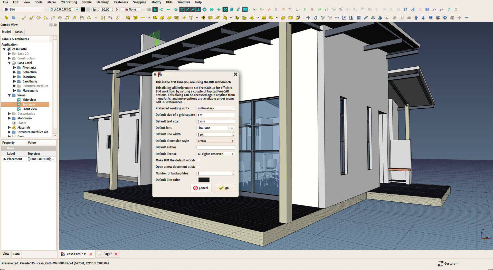
This is an experiment I am currently working on, and that you can already test. It is basicalyl an effort to re-think the whole organization of BIM tools and workflow in FreeCAD, with the aim of making it easier to learn and use. The basic idea is not to modify any of the existing tools of FreeCAD, just gather them in a more intuitive way, and provide a couple of useful macros to glue it all.
If using FreeCAD 0.17, you can test it immediately by installing it from menu Tools->Addon Manager. Or manually from here
So this workbench is, at the moment, a collection of tools from several workbenches: Draft, Arch, Part, Flamingo and Fasteners. There will be more later on. On top of that, a simple "setup" screen that will set all the most common FreeCAD settings used for BIM, and later on a couple of interesting macros from the Macros repository.
As I often say in these reports, building User Interfaces for BIM or CAD work is a very complicated task. Simple tools, like Sketchup or TinkerCAD have very good, simple and intuitive user interfaces. In FreeCAD, especially when dealing with BIM, we deal with much more complex situations. If we look around, other BIM apps also have very complex interfaces, and the learning curve is also steep. And when you look at, for example, BIM plugins for Sketchup, you also see that the complexity raises very quickly.
So there is no easy, straightforward answer to "solve" the steep learning curve of FreeCAD. But that doesn't mean nothing can be done either. But it needs some experimentation and step-by-step improvements. That is precisely what I want to achieve with this workbench: Find the good parts that run well, identify what doesn't work as smooth, and what can be done. It's all about details. The rest, the technical part, will stay in Arch.
I had this aim for the Arch workbench at first, to be the "all-in-one" BIM solution of FreeCAD. But the exponential growth of the addons being developed around FreeCAD, made me rethink that approach. The Arch tools, as said above, begin to be reasonably solid. They lack some polish, and better interface. That will be a main focus point for me this year. But it might be time to also think better in more global "BIM workflow". I have no clear idea of what that would be, that is the reason of existence of this new workbench.
Another motivation behind this is also to split things more between the "technical" part (the Arch Workbench), and the "interface" part (the BIM Workbench), and make the latter much more simple, so hopefully more people will be able to contribute to it, without having to merge much into the FreeCAD source code.
So, please use it, test it, be aware that it willbe an experimental test bed so it might change often, and share with me any thought you might have (that is reasonably doable, please!) to make the BIM workflow better, and the learning curve smoother.
Cheers!


Great to hear that, do you mind recording some tutorialfrom above simple buildings?
Cheers,
FreeCAD Arch development news - January 2018
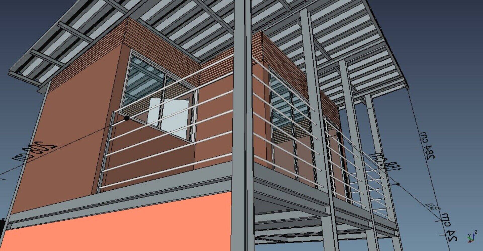
Hi everybody,
Sorry about the late news again, but it would have been a pity not to include a fresh feedback from the FOSDEM that happened this weekend. So here are the main topics that happened in the last month. Once again, thanks a million to eveybody who helps the effort by contributing to my Patreon campaign or on LibrePay. Not only it's highly appreciated, but it allows to do more and more long-term planning, and 2018 promises to be rich in BIM features in FreeCAD. I also believe we are really closing the gap with commercial BIM apps out there.
FreeCAD 0.17 release
Since FreeCAD is close to the next official release, that we plan to unleash this month, the development is now in "feature-freeze mode", which means nobody is adding new features (to avoid the risk to break anything and introduce new bugs) and instead concentrates on fixing bugs. Consequently, this month was pretty low on new features, so there won't be much appetizing BIM stuff to show here. On the other hand it was intense in coding and bug fixing.
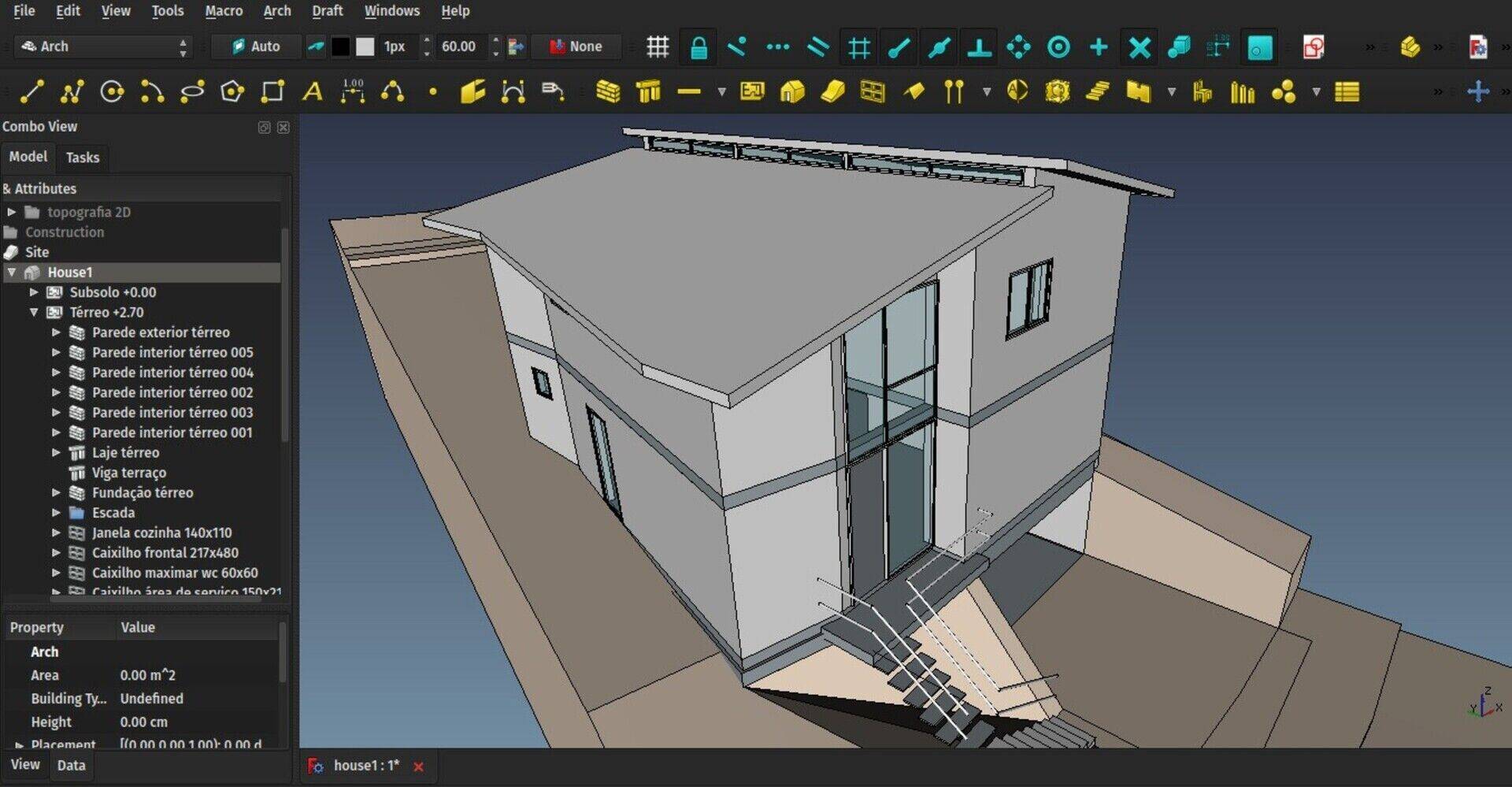
Basically I have been busy thoroughly testing the BIM functions and workflow in FreeCAD, and fixed a lot of bugs on the way. I think it is now pretty stable, more than it has ever been in the past. Also all the main Arch/BIM objects (Walls, structures, windows, etc...) now have their base code pretty well consolidated and reliable, so the next step, which is working on making them a bit more user-friendly, can now begin.
To do this testing, I have built 3 house projects with FreeCAD. The internal organization of these files differs a bit from one to the other, but they are all pretty simple. I think they show well the "stage" you can now reach with FreeCAD easily and reliably, and extract from it all the data you need (2D drawings, decent IFC files, spreadsheets/schedules, and mesh models for rendering). Not yet a full large-scale building with all its details, but we'll get there.
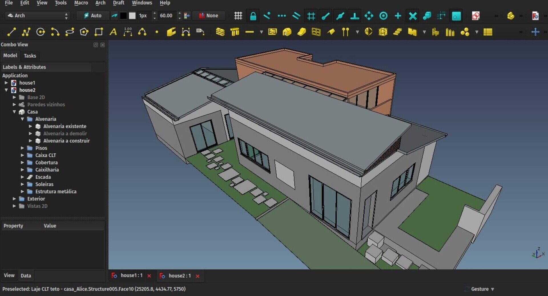
In any case this is already a full BIM workflow, all objects are parametric, all export to IFC with all the properties you wish to add to them, everything can be modified, and the 2D drawings update automatically (or not if you choose not to, to have a faster workflow).
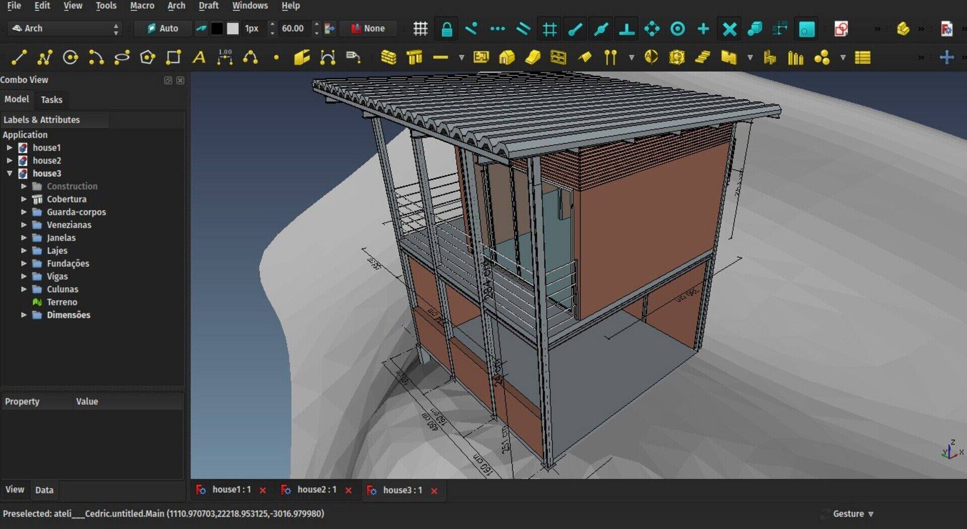
You will notice that these models don't use TechDraw for the 2D views, but that is because I specifically needed DXF files from these 2D views, which are at the moment easier to produce with the Draft workbench.
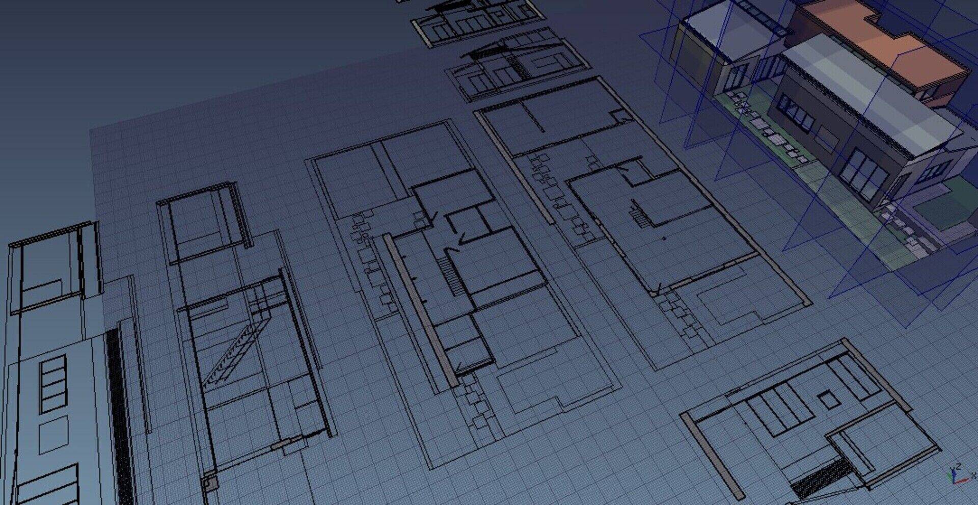
But that doesn't mean TechDraw is not up to the task, far from it. If you wish to produce good-looking documents right from within FreeCAD, give it a try, it works impressively well already.
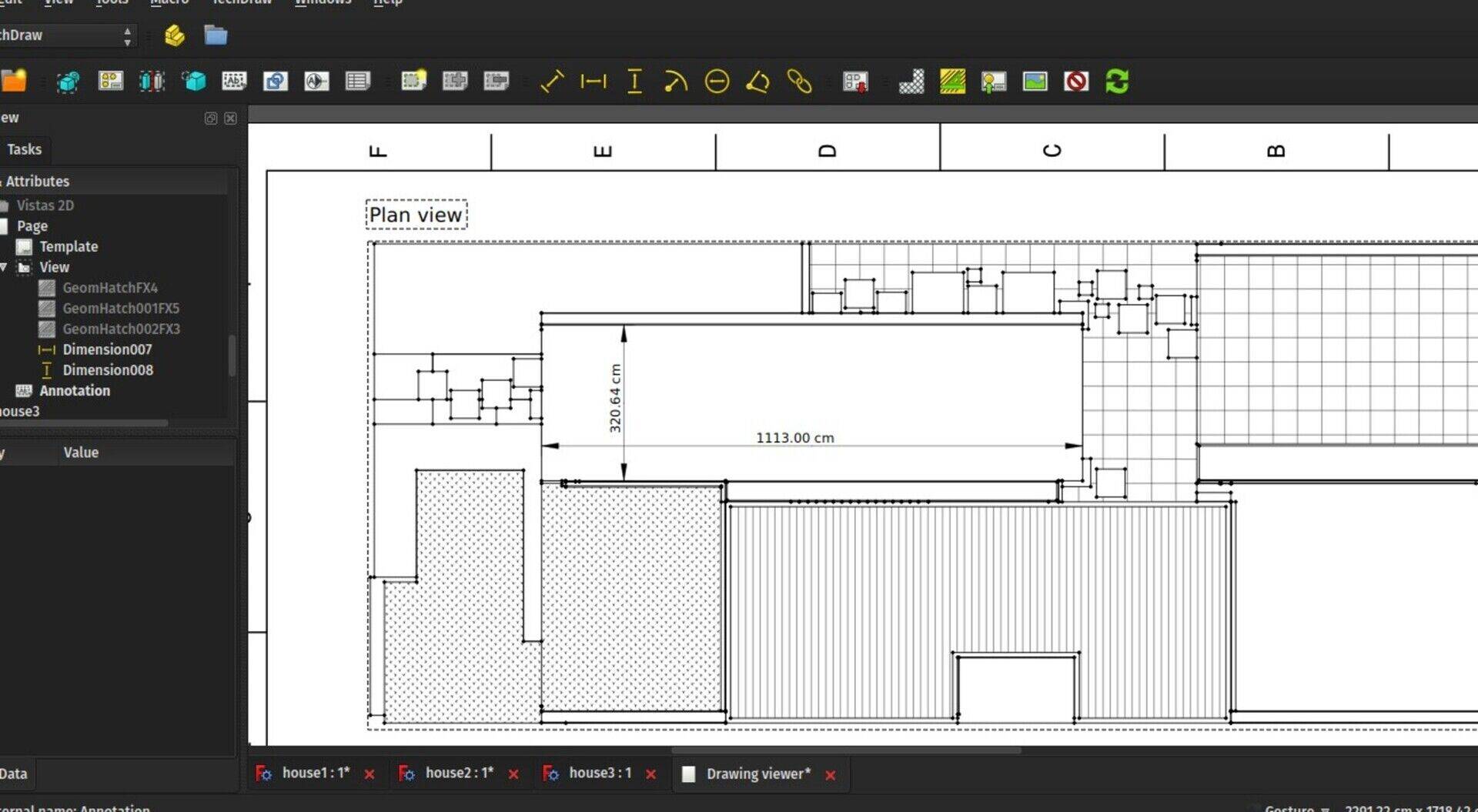
If you would lik to have a look at the files, here are House 1, House 2, and House 3.
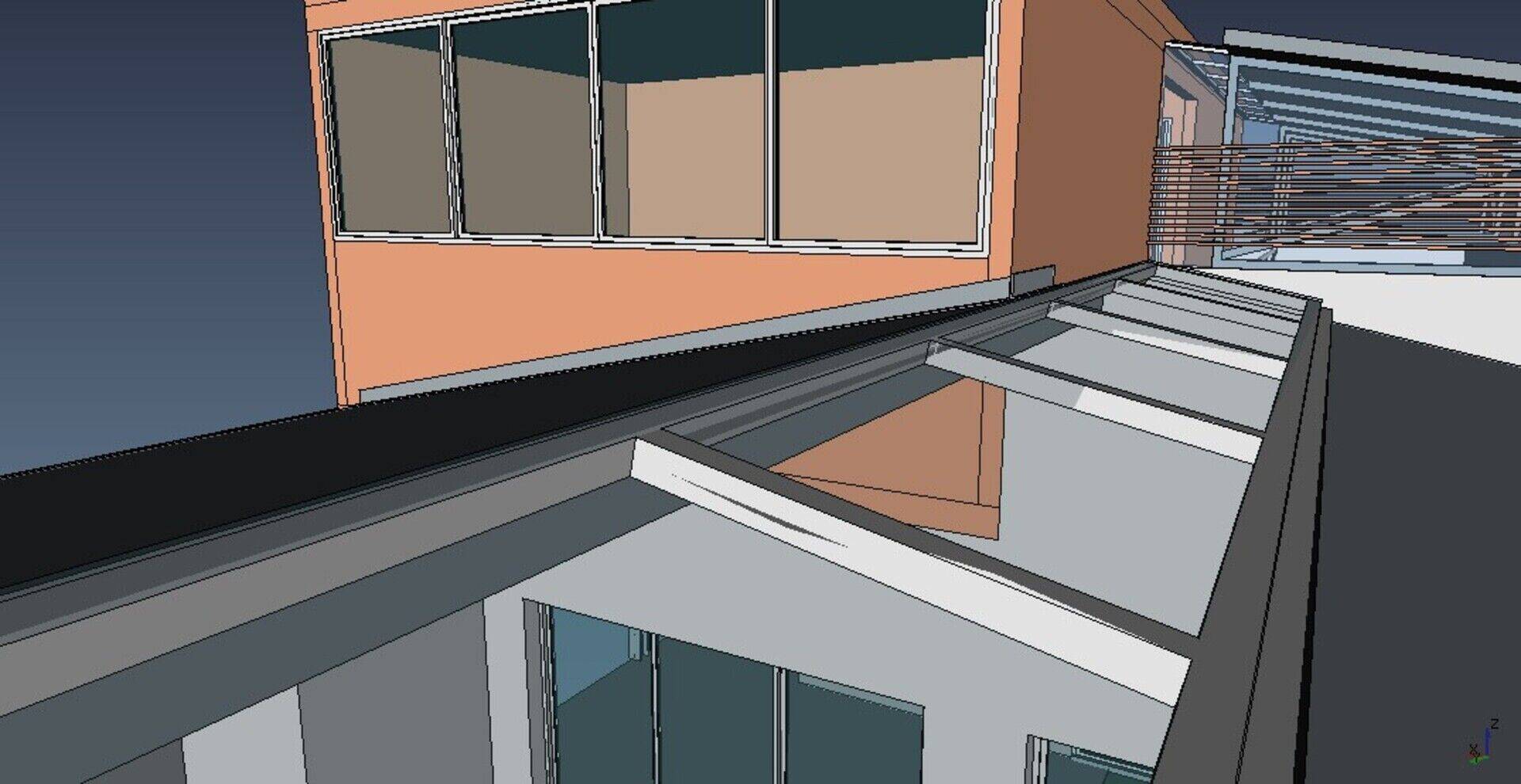
There are also several interesting things that are available to you due to the very generic nature of FreeCAD, that are sometimes hard to obtain in commercial apps, such as mixing 2D and 3D elements in your models. You can easily keep these 2D elements out of IFC export (or not, your choice), simply by grouping things the way you like best. In FreeCAD, you don't really need to use Floors/Storeys/Levels. You can, if you need (for example to produce sounder IFC files), but you can perfectly well stick with groups. I often think BIM and IFC files would give much less headache if everything was simply properly named and organized.
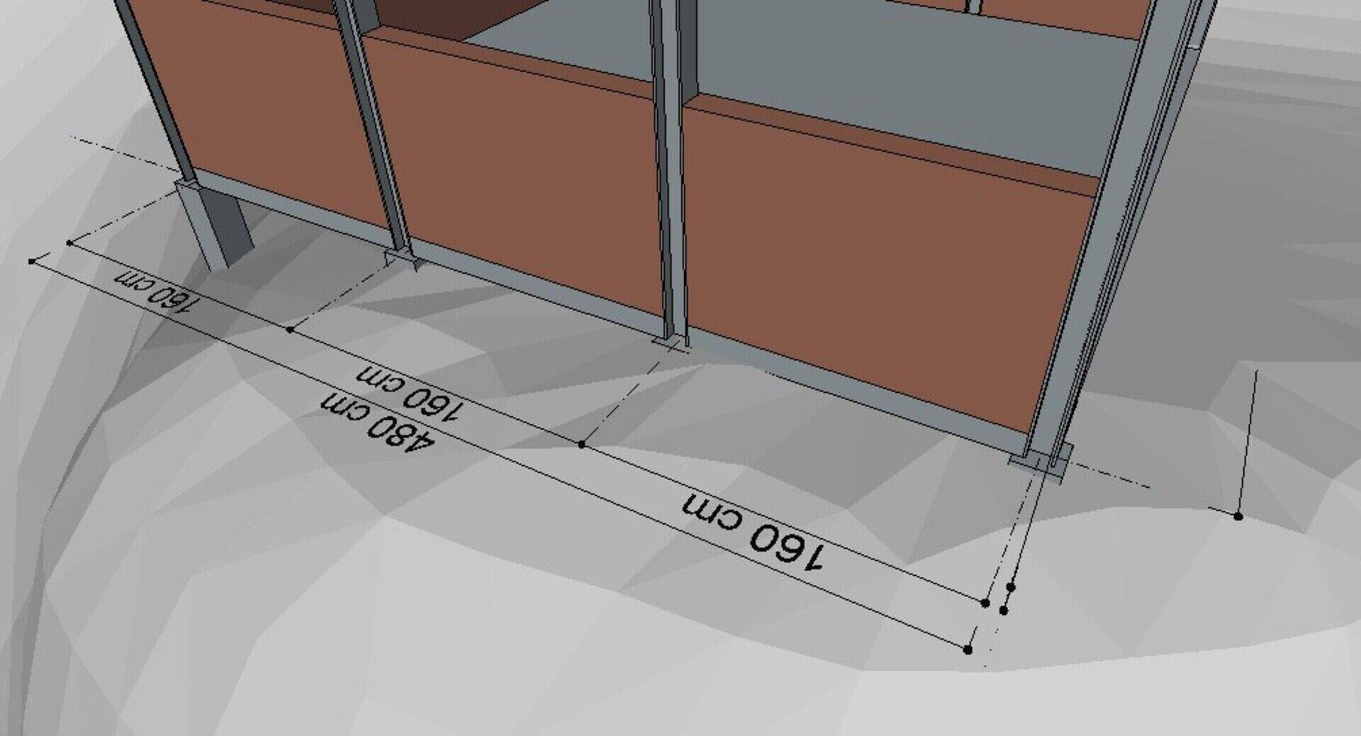
The whole cycle of placing section planes, getting 2D views from it and exporting them to DXF/DWG is now pretty straightforward and hasn't given me anymore problems recently. Draft Shape2DViews objects now have a switch to disable automatic recompute, so they won't be recalculated automatically everytime you change an object, which can have a huge impact on performance if you have a lot of views. You can then recompute them manually whenever you want.
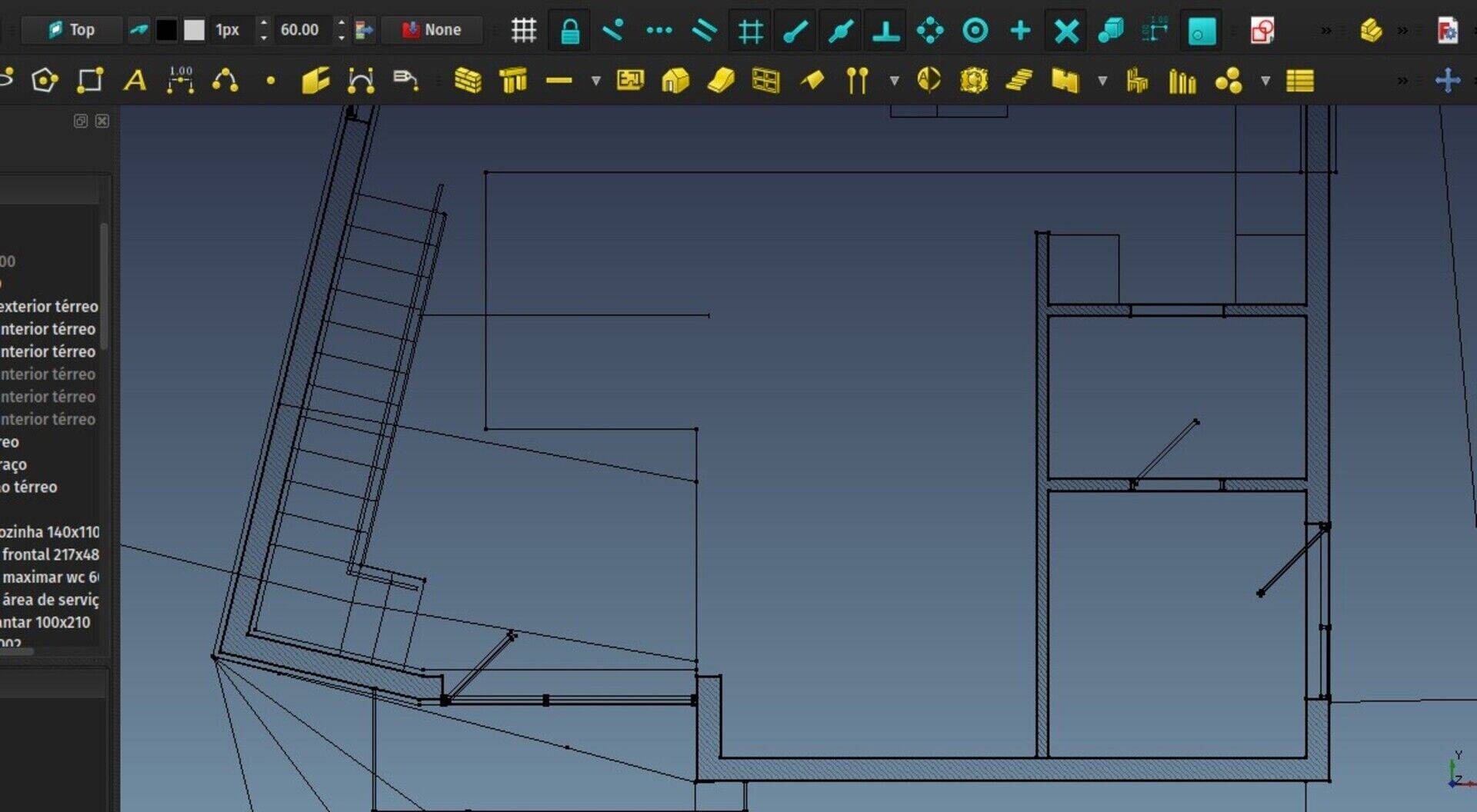
Help needed!
As we are coming close to our 0.17 release, there are a few areas which would welcome some help, if you have a bit of time to spare. The main one is to finish the translations, so we can include them in the release files. As I'm writing this, 6 languages are fully done already, and 10 others are at more than 90%. The other 34 also need some love. We won't wait for all of them to reach 100% ofcourse, but the more we get, the better!
There is also currently heavy work being done on the documentation to update it with all the latest changes that have been added mainly to FEM, Path and TechDraw, and to make it easier for users of earlier versions to make the transition to the new Part Design workflow. If you know some of these tools reasonably well, please help us to make sure the documentation is accurate and up to date!
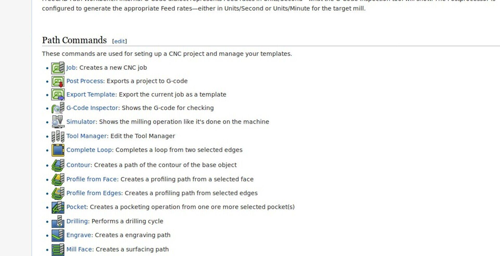
FOSDEM
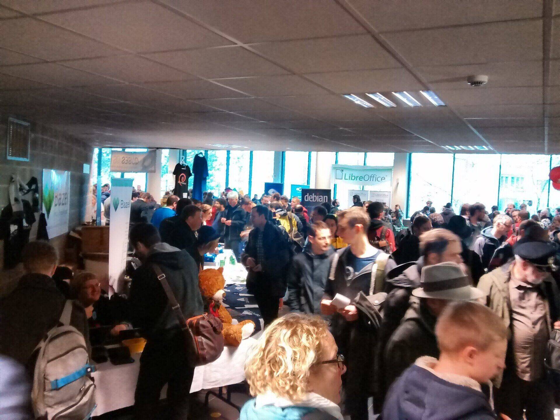
So this weekend I was at the FOSDEM in Brussels, and gave a talk about the WikiLab project we've been doing last year, and how FreeCAD was used in it. The talk went pretty well, lots of people in the room (some FreeCAD forum members were there!), and very interesting questions raised. Thanks to FOSDEM blazing fast video processing, the recording of the talk is already available (the slides are here):
Right-click -> Play to play the video above or watch it here
Other than that, I watched a couple of talks (a big part is online already, browse here), hanged around the different booths, and because the FOSDEM is so huge, couldn't meet almost anybody I knew was there.
I got a bit surprised how the FOSDEM is still predominently a male event (around 95% males, my own estimation), while many IT/open source events around the world (FISL in Brazil for example) are very close to 50/50%. Mystery... But there were fries!

That's it for this month, stay tuned for the FreeCAD 0.17 release annoucement (or follow it on the forum), and after that, expect new BIM features to land in!


@Willem yeah, that's highly overdue... But check out Regis's videos, there is a LOT of amazing content https://www.youtube.com/user/RegisBBNT/videos
@Zbigniew yeah just saw that too! Not sure how to make use of it though...
Usable but surely would need rewriting a lot of code?
Thank you for your reply.
I must admit I got a lot of appreciation for you as an architect who could learn programming the tools for architecture )). As to FC workflow: I made a few 'approaches' to arch.module, having some earlier experience with revit, archicad, autocad architecture etc. and just could not figure out FC arch. workflow so far ))). But I take your promise as a good sign and wait for FC 17 release. Btw. Best New Year, 2018 wishes !


