Categories:
-
3d 96 articles
-
animations 16 articles
-
architecture 47 articles
-
blender 98 articles
-
bédé 19 articles
-
techdrawing 24 articles
-
freecad 190 articles
-
gaming 1 articles
-
idsampa 8 articles
-
inthepress 8 articles
-
linux 57 articles
-
music 1 articles
-
nativeifc 31 articles
-
opensource 267 articles
-
orange 4 articles
-
photo 16 articles
-
projects 35 articles
-
receitas 176 articles
-
saopaulo 18 articles
-
sketches 163 articles
-
talks 25 articles
-
techdrawing 24 articles
-
textes 7 articles
-
trilhas 3 articles
-
urbanoids 1 articles
-
video 47 articles
-
webdesign 7 articles
-
works 151 articles
Archives:
-
2007 22 articles
-
2008 32 articles
-
2009 66 articles
-
2010 74 articles
-
2011 74 articles
-
2012 47 articles
-
2013 31 articles
-
2014 38 articles
-
2015 28 articles
-
2016 36 articles
-
2017 41 articles
-
2018 46 articles
-
2019 59 articles
-
2020 18 articles
-
2021 20 articles
-
2022 7 articles
-
2023 25 articles
-
2024 15 articles
FreeCAD BIM development news - September 2021 - The big 2D upgrade
Hi all!
I know, there has been almost a year since last FreeCAD BIM development update (I have written a couple of related articles on the way, though). There are several valid reasons to this, basically I've been quite busy with more administrative stuff with FreeCAD, but I'm afraid it might also be due to shameless natural laziness...
Anyway, here we are finally, and since I also haven't stayed without coding, I dare to say there is a lot of new stuff. There is (much) more to come too, but that's for another report...
Most of the coding I've been doing this year is aimed at improving the BIM model to 2D process. This is one of the areas of FreeCAD that still didn't offer a really fluent workflow, and one of the most sorely needed area to be able to use FreeCAD as a full BIM platform.
If you ever used Revit, I often think Revit is no so good for modelling, but it is a real pleasure to produce views and annotate them. It's fast and convenient to place dimensions, texts and all these annoyances that you often find in other CAD apps, like configuring texts and styles, is really simple and out of your way so you can just place and align annotations.
I dare say we're there with FreeCAD too now, and we can produce 2D documents as good as any other CAD or BIM app, and with basically the same speed and ease. Most of the features below are rather small, but together they make the whole workflow much better and comfortable.
Thanks a million to each of you who support me on Patreon or Liberapay, specially for your patience while I wasn't writing anything here. As things are getting a bit calmer for me now, I'll try to resume posting once per month.
So here we go!
Foreword
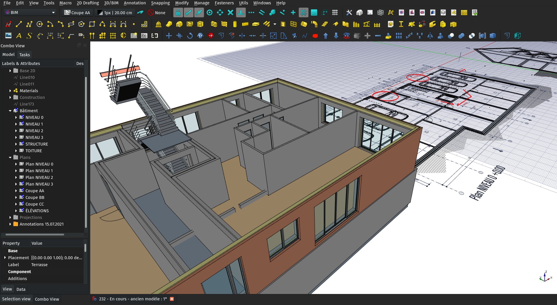
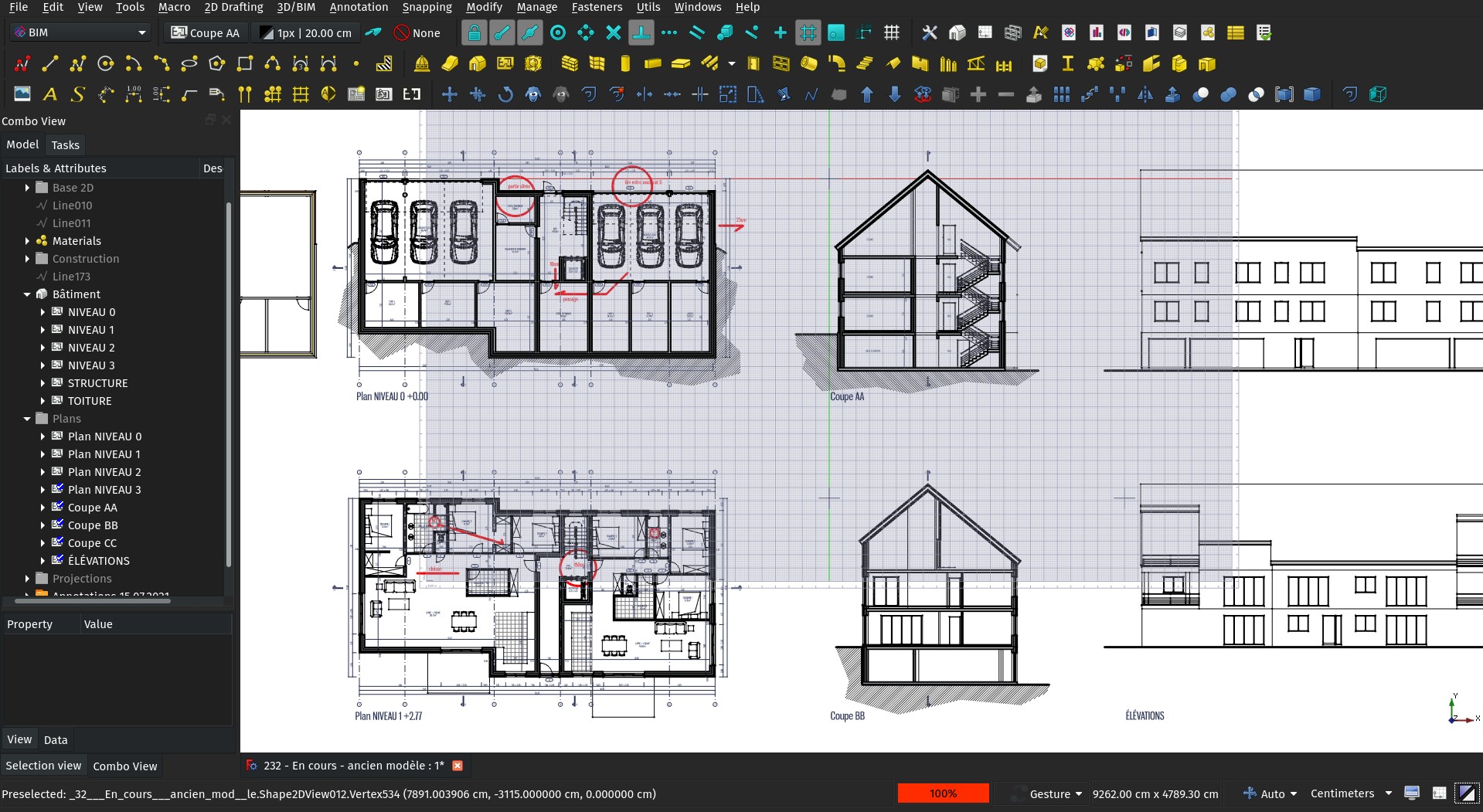
Almost all the features presented below deal with a BIm -> Draft -> TechDraw workflow. That means, there is an intermediary, Draft-based step between your BIM model and the final TechDraw page. The typical workflow is:
- Model your building using BIM or any other FreeCAD tools
- Use Building parts for your levels (not mandatory, but they carry an automatic, built-in section plane)
- Place Section planes where you want sections and elevations (and plans if you didn't use Building parts)
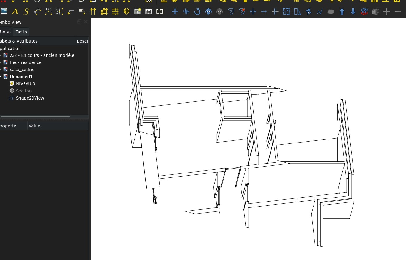
- Create Shape 2D views from your Building parts and section planes
- Create other Shape 2D views for views that cut through your model, and set them in Cut Faces mode. That way, you can give a different aspect to viewed and cut geometrty
- Annotate these views with texts, dimensions, symbols, hatches...
- Put everything related to one view (Shape 2D views, annotations,...) into one same group or Building part
- On a TechDraw page, create a TechDraw view from that group or Building part.
This might seem annoying, unneeded, counterproductive. But it turns out to be very fast. It separates the whole computation (which is the main speed hog in the process) into two distinct processes: 1) The sectioning of the BIM model to obtain 2D views, and 2) the turning of that 2D data into TechDraw elements.
By inserting all the annotation phase in the middle, between these two operations, we make it depend on only half the computation. And in turn, since everything is 2D already, the second step is very fast. You also get a much more reliable DXF/DWG export possibility, at the view level.
This is also not different than what many other BIM applications such as Revit do, where there is an intermediary "view" system between your model and the final page. This is exactly what we're aiming at here.
The only difference, up to now, is that your 2D views live in the same space as the BIM model. This has its advantages too (one can easily snap between the two, etc), but at some point it probably won't be too hard to separate the 2D contents into dedicated views.
I really encourage you to explore this workflow. I have used it for several projects now, and it turns out to be very stable, fast and powerful.
Here are the improvements I've added these last months:
"Apply to dims/texts" button
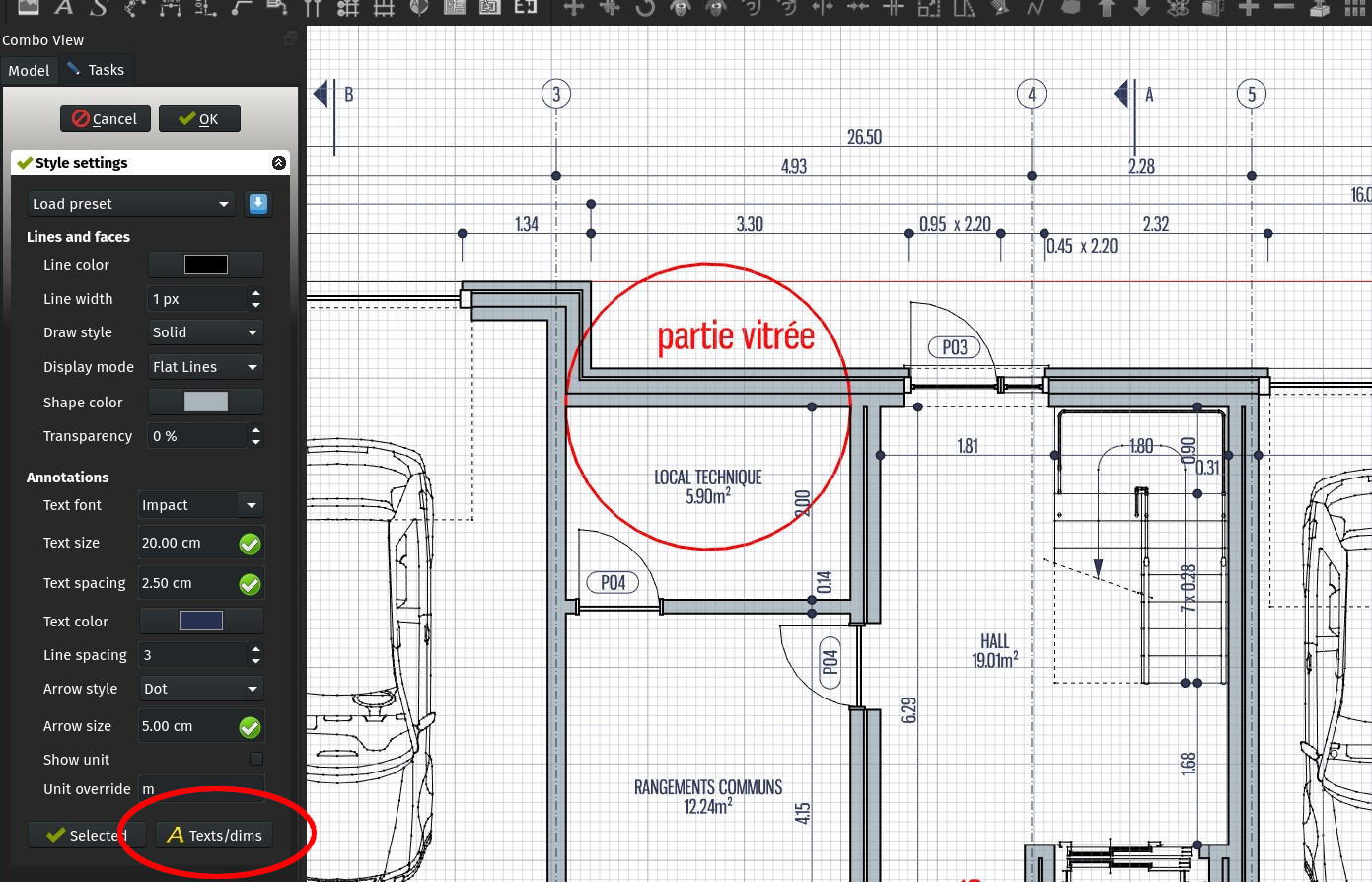
The Draft styles dialog allows you to quickly set up a style for texts and dimensions. It now features a new button at the bottom, that applies the style currently set in the editor to all texts and dimensions in the active document. If you are using different styles for, for example, different clients or jobs, this allows to quickly convert one document to another style.
BIM Leader tool
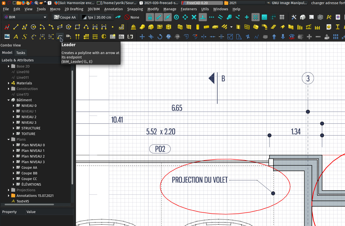
This is a very simple tool, now available in the BIM workbench: It is simply the same Draft Polyline tool, but it will automatically add an end arrow (following the current dimension style) to it and take the text color instead of the normal line color.
This makes it really easy to place leader annotations: Place your text first using a common Draft Text, then use it tool to place a leader line, starting from your text and ending where it should point at.
Of course there is already a Draft Label tool, that achieves ore or less the same result, with a couple of advantages (the text can be automatic, and the text stays "attached" to the leader line), but I found this workflow very fast and flexible, since the leader lines are simple polylines. For example, you can edit/stretch several of them at once, or delete them without deleting the text, etc.
Move TechDraw views
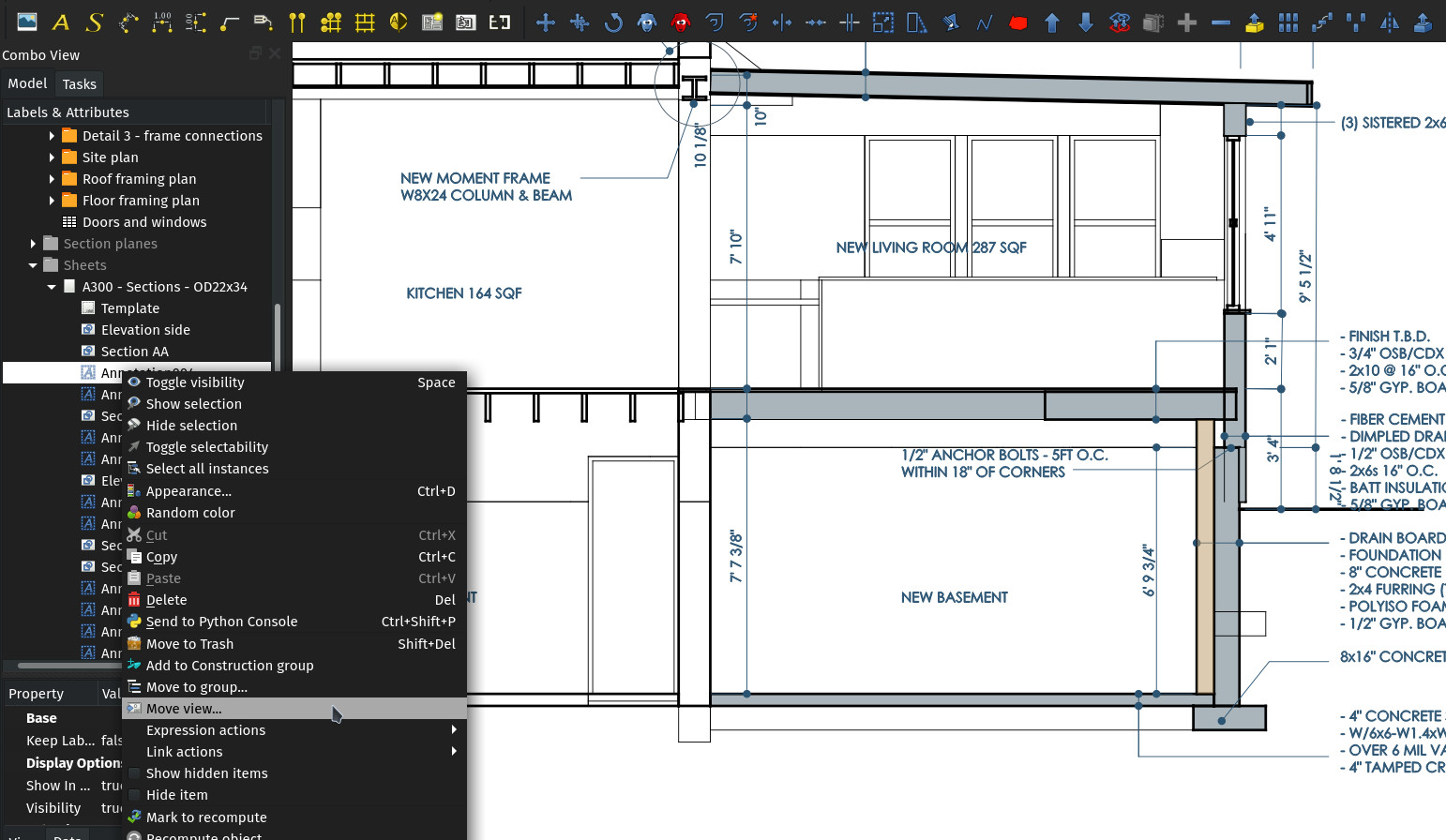
When you begin to deal with multiple TechDraw pages, you begin to need to do a lot of copy/pasting operations, for example to duplicate view titles and annotations. The main problem is, when you copy/paste a TechDraw view, it lands in the document root, outside a page. If you add it to a page via Python (myPage.addView(myView)), not only it is tedious, but its position is reset to the center of the page.
Now, in the BIM workbench, once you have pasted a view (or even with any other view), right-clicking it shows a new Move to page... option, that allows you to pick an existing page to move the view to. Position won't be reset anymore.
Background color switch button
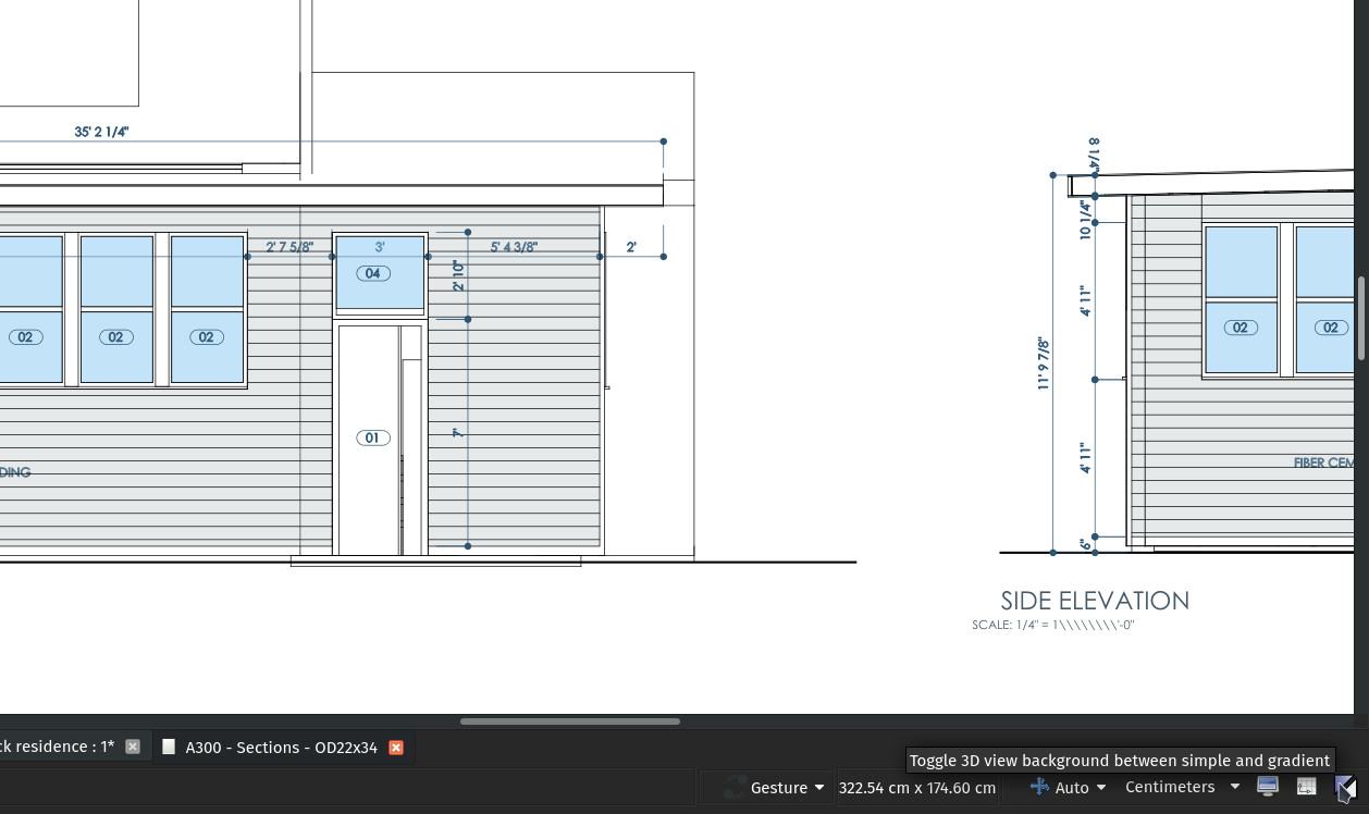
If you are like me, sometimes you like to use the world-famous FreeCAD gradient background, mostly when looking at the model in perspective view, other times you prefer a flat, white (or black if you are AutoCAD-nostalgic) background. But the process of going through the preferences screen is tedious.
Cry no more! The BIM workbench now features an easy button to switch between the two. Make sure both gradient and simple colors are correctly configured in preferences, and you're set!
Create Draft texts when using the C++ DXF importer
The new default C++ DXF importer of Draft was still creating older Annotation objects from the texts found in the DXF file. This usually gave poorly looking imports, with wrongly configured texts. The importer will now create Draft Texts instead, which correctly take your current styling settings. Your DXF files will now look immediately more decent on import!
Texts are now supported by Draft Edit
The Draft Edit command is one of those versatile commands I use all the time. It works similarly to Blender's TAB key to switch between object mode and edit mode (I gave my Draft Edit command the E,E shortcut, it works pretty well for me). It works with almost all Draft objects, but one was missing: The text object. This is now solved, when edited, the text will show you the same edit task panel used at text creation. This alone is a huge speed-up when working witch a lot of annotations.
Edit order tool
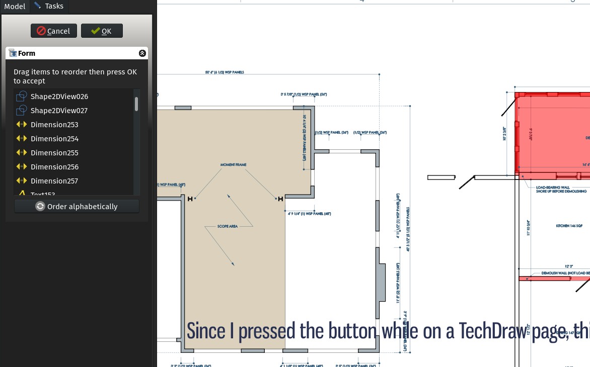
Similar to the Path Group tool, the BIM workbench now adds a right-click option to reorder the contents of groups (or any other object with a Group property, such as Building parts). Upon choosing that option, a task panel opens that allows you to reorder child objects by drag-and-dropping them. You can also sort the children alphabetically automatically.
This has cosmetic uses, only to reorder your model contents and keep things better organized, but it has another very important use: When producing a TechDraw view from a group of 2D objects, the order is important. As that view is created in SVG format, each object is added to the SVG result in the group order, which means the first objects are drawn before the next ones. Some objects can therefore hide other objects that come earlier in the list. This is usually not a problem if the view is made only of lines, but can be a problem if some of the objects have faces.
With this tool, it's now possible to replace everything in the right order and obtain perfect-looking TechDraw views.
Fix non-XY text positioning in techdraw
When projecting texts that weren't directly drawn on the XY plane on a TechDraw view, there were often problems, and objects with automatic text, such as Spaces, were often not drawn correctly when viewed in non XY projections (in section views, for example).
This is now fixed and much more reliable. Space labels are now drawn at the center of the space by default, when viewed in non-XY directions.
Support for global DXF variables at export
The DXF exporter of FreeCAD is now able to write global DXF variables, which allows us now to export basic document-wide things like default text or dimension styles.
Grabcad BIM library tool
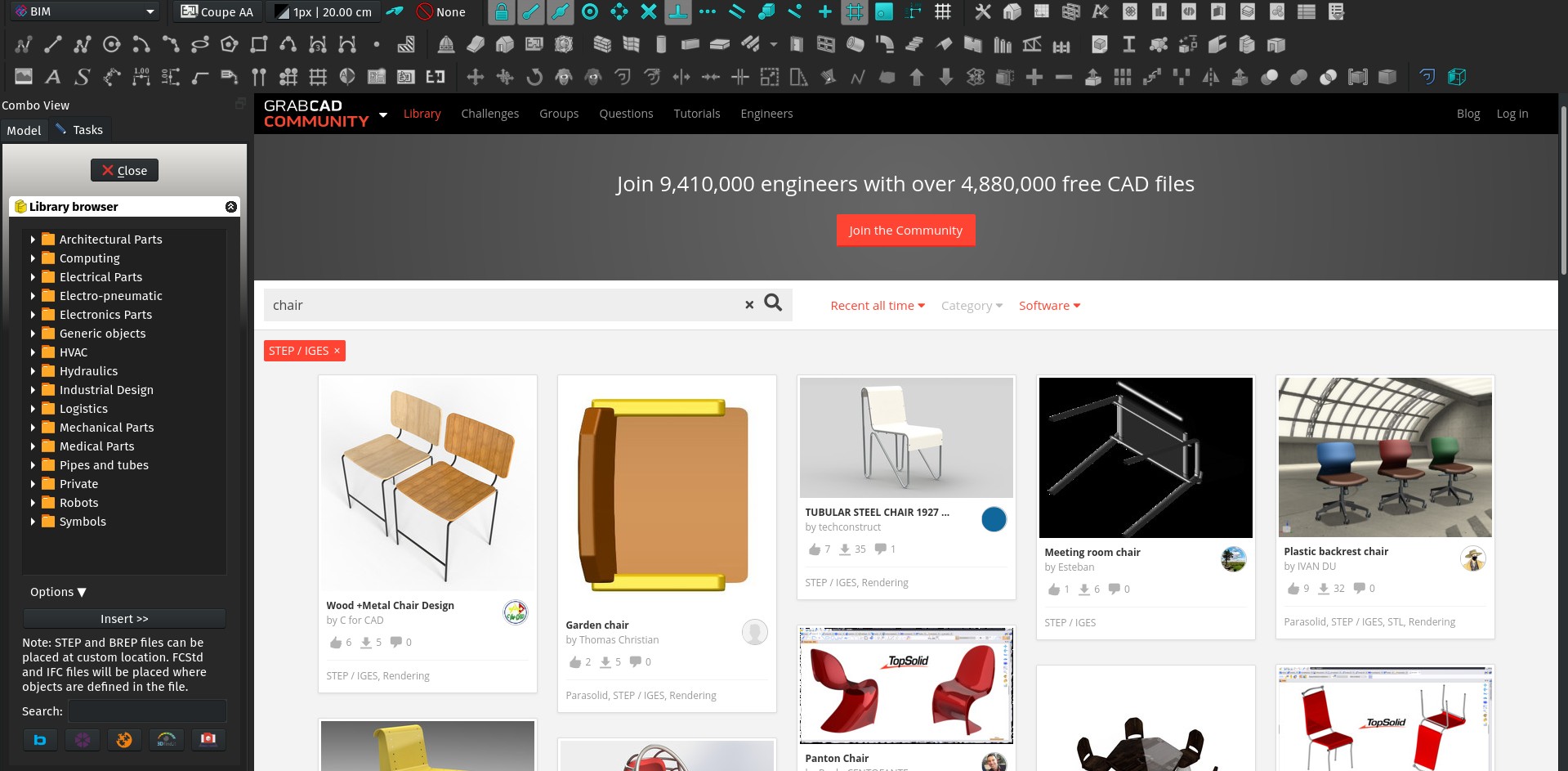
Even with all the BIM objects sites out there, most of which already supported by the BIM Library tool, it is still hard to find proper, well-modelled BIM objects such as appliances or furniture for FreeCAD. On most of these sites, objects are published under proprietary formats, and the IFC version they propose is a low-quality mesh export that is almost unusable.
GrabCAD, which does a lot in the CAD world but is often unknown to BIM people, also manage a very interesting objects library fueled by user contributions. Although it is not principally BIM-oriented, objects are often well modelled and published in reliable formats. By browsing their library and activating the STEP/IGES filter, you will encounter objects that import with a very high quality into FreeCAD. I would definitely recommend looking there when you need basic, default objects such as chairs, sinks, washing machines, etc.
From the BIM Library tool, you can now search directly the STEP/IGES-enabled objects on GrabCAD.
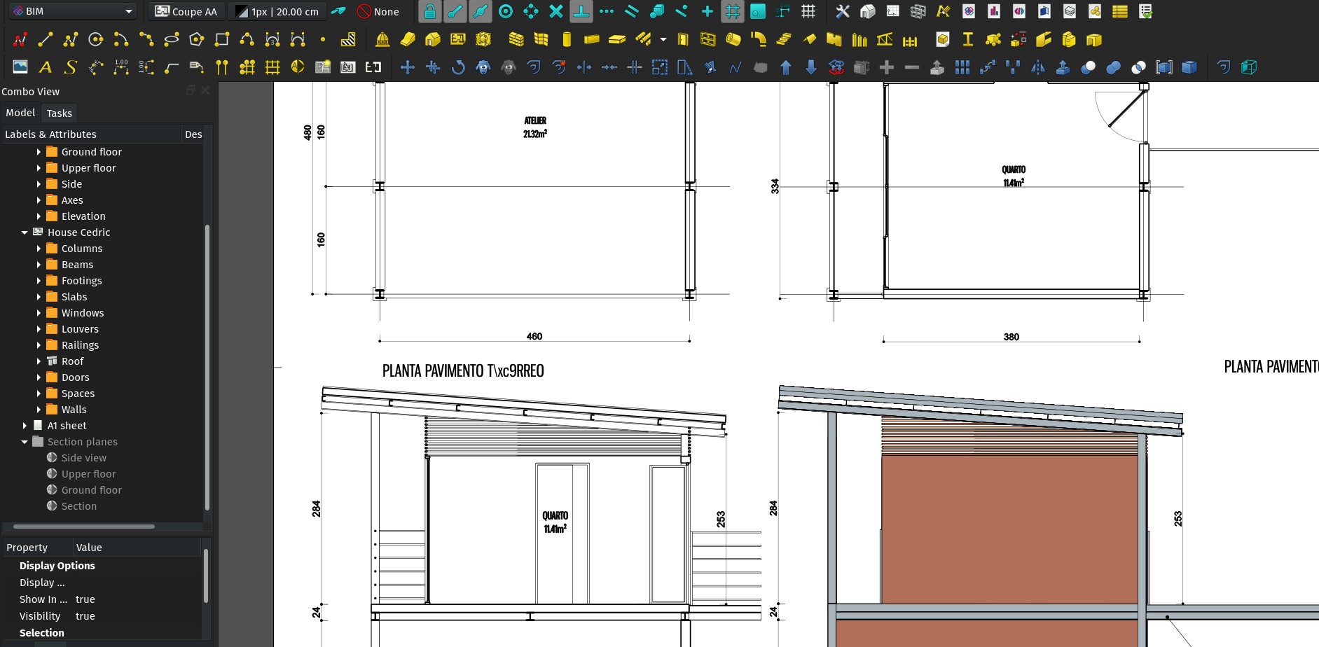
Horizontal / vertical dimension tools
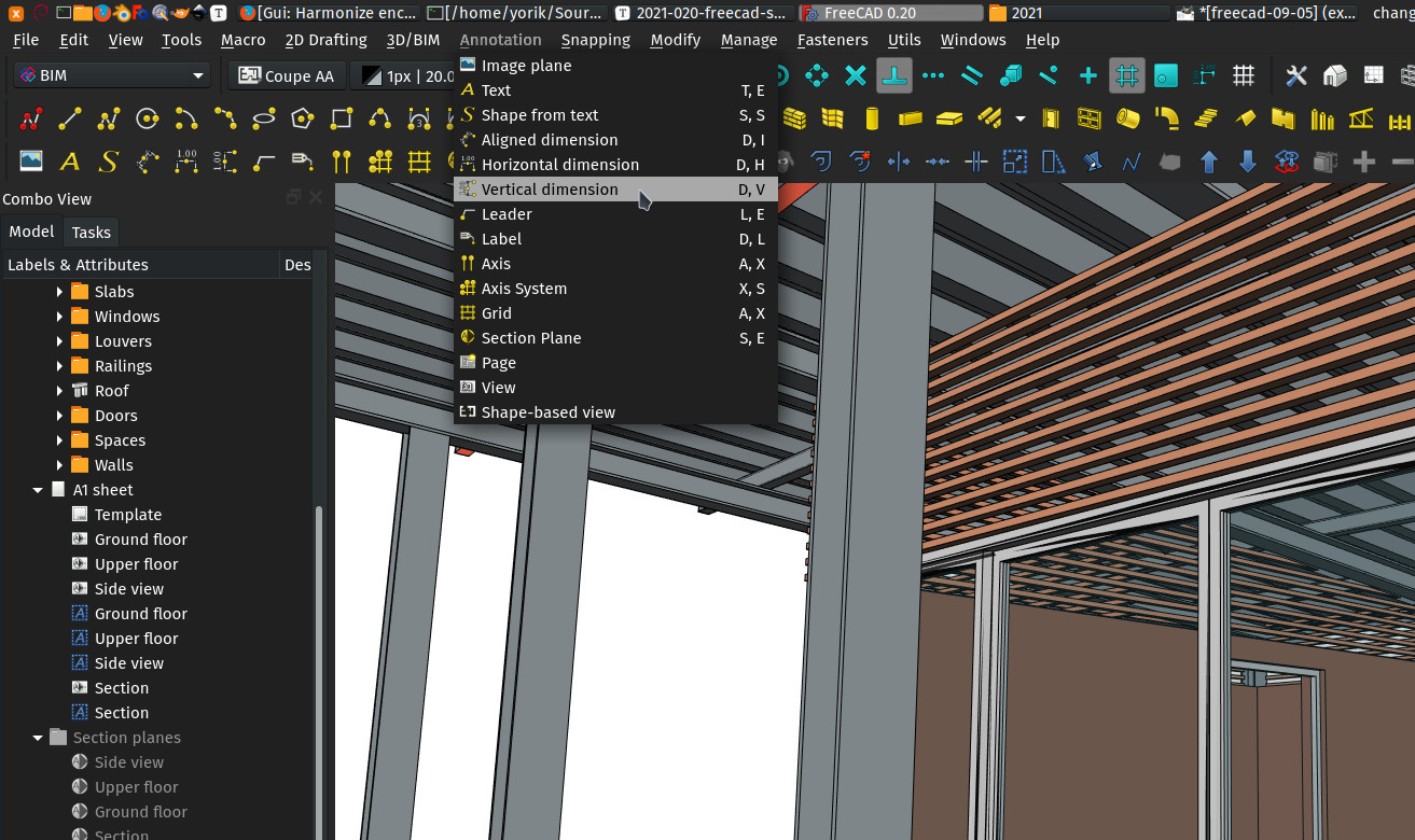
This is a very small cosmetic tweak, but sometimes these have a surprising impact on the general workflow and drawing speed... In he BIM workbench, the Dimension icon has now been split into three: Horizontal, vertical, and free-directional (aligned). These three buttons execute the same command, but start it with different setups. The former, free-directional tool is still there, and it still allows you make horizontal or vertical dimensions too, by pressing SHIFT while drawing.
Alternative BIM Icons for arch component, draft shape2dview, page and view tools
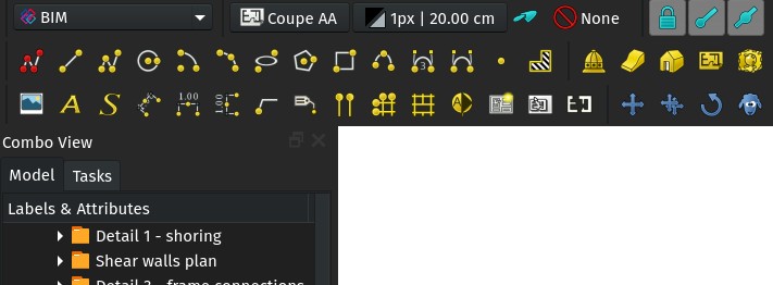
This is another cosmetic fix, but since I'm trying to promote the BIM to Draft to TechDraw workflow, changing the icons to reflect that workflow more has its meaning.
These changes are only in BIM so far so people can test, but the idea is of course to unify everywhere later on.
Imperial scales macro
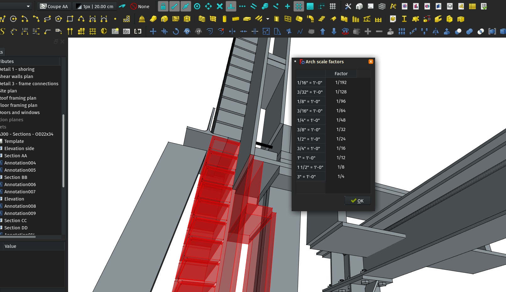
This is a very simple-and-stupid macro that prints a table of common imperial drawing scales, and the corresponding factor to be used in TechDraw views.
Should we embed this somewhere? Any idea how?
If you are interested in the making-of, this macro was simply created with QDesigner, then converted to a PYthon script using pyside-uic and the two last lines were added to make the dialog show when the macro is run.
Load/save Draft styles
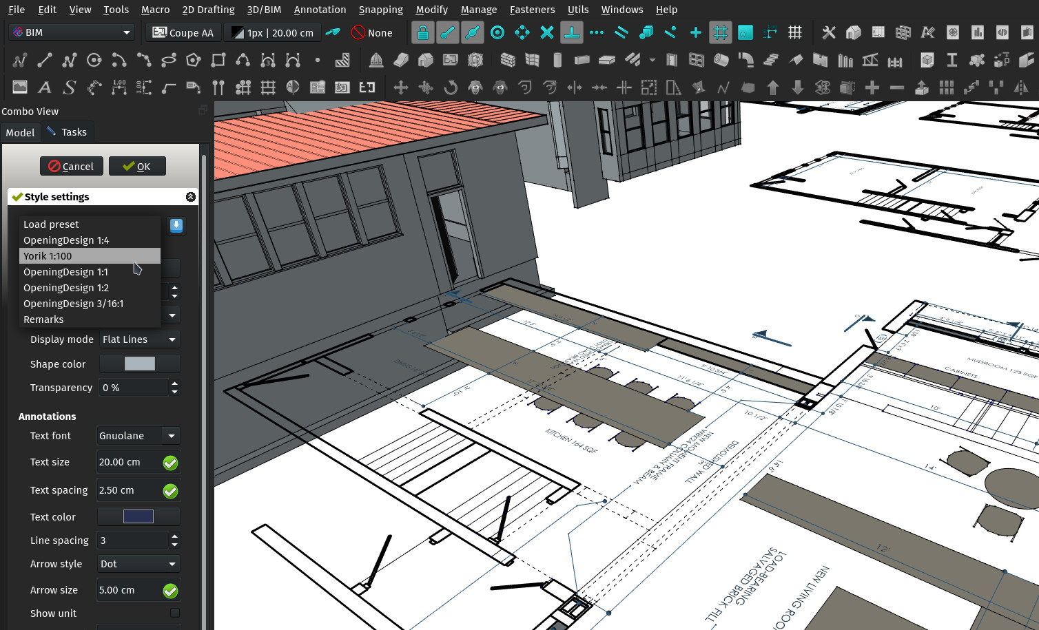
The Draft styles panel has gained load/save preset buttons, so you can save your styles for future uses. The styles are saved in a .json file that is located in your FreeCAD user folder and is easily editable.
Arch References can now fuse base objects by material
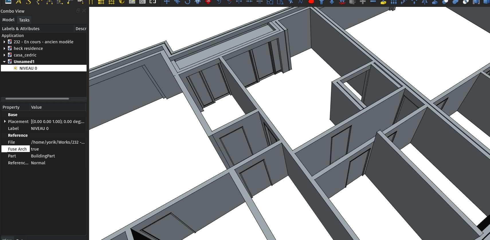
When using an Arch Reference object to include a Building Part, there is now a new property on the reference object to fuse the shape geometry by material, so all solids that share a same material in the referenced file will be fused together, the same way as what was already available in the TechDraw Arch view. This is typically useful for walls, for example.
This allows you to separate completely your BIM model in one file, and the 2D drawings you create from it in another file. The files are therefore smaller, and there is also less computation happening, which gives a big boost in speed and comfort.
SWAG page
Want your own, official FreeCAD t-shirt? Yes, we now have a swag page!
It's not a webshop, mind you (we don't have the resources to maintain one just yet), just DIY instructions to get your very own.
Section depth settings
The section plane object has gained a new Depth property, that indicates the maximum distance this section plane can consider. If you set a non-zero value there, the viewed objects will be clipped out past that distance.
Section plane marks
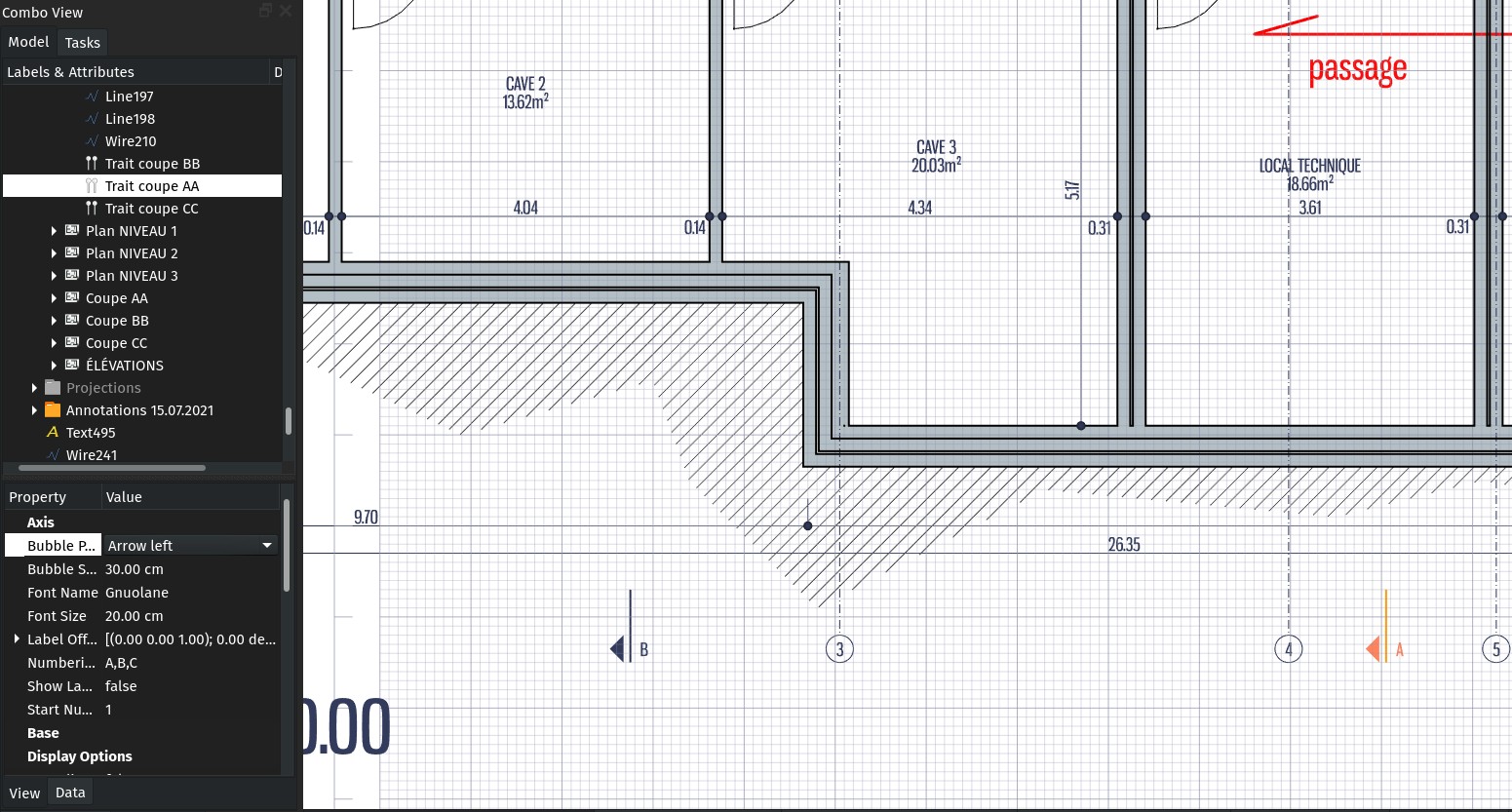
I added a couple of new modes to he Arch axis so they can be used to represent secton marks on a 2D drawing. By setting their Limit property, the axis will be displayed as two short lines at each end instead of a continuous one. By setting their Bubble style to bar or arrow, they will appear as a section mark.
This will appear correctly on a TechDraw page, but I still have to adapt the DXF exporter to support it.
This is just a 2D symbol, and is not automatically tied to a section plane,for example, but that should be pretty easy to do, in most cases it's just a matter of tying the X position of the axis to the X position of the section plane.
Shape2Dview exclusion points
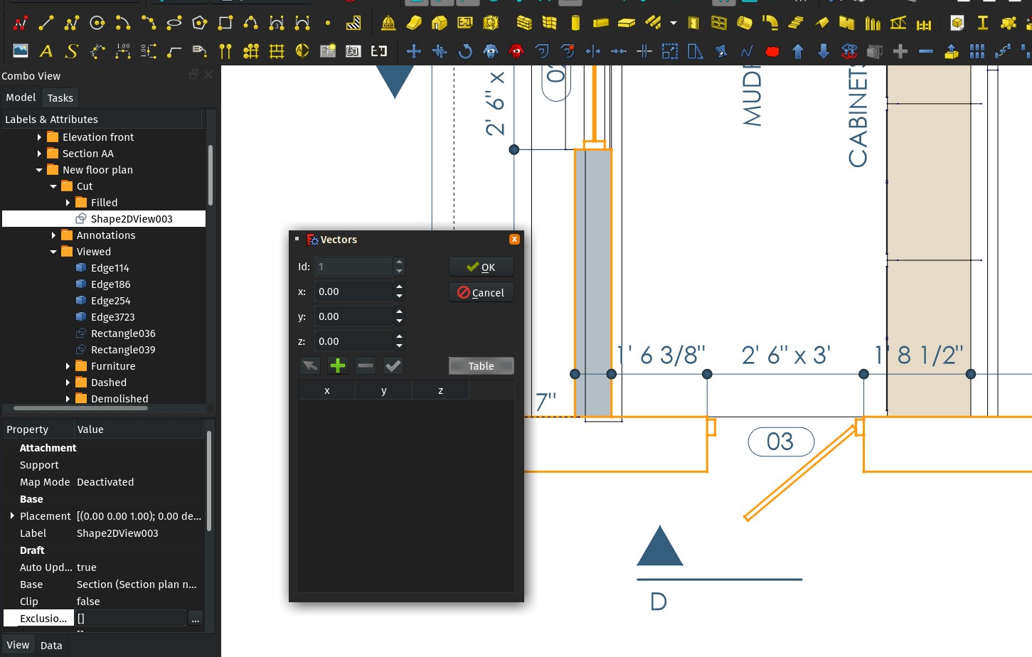
This is a kind of experimental hack, but it could turn to be pretty useful: The Shape2Dview object has gained an Exclusion Points property, where you can indicate a list of 3D points. Any line of the Shape2Dview that passes through any of these points, is not drawn.
This basically allows to hide lines of a Shape2Dview. It is still a bit cumberstone to use, should certainly gain a good UI to set/manage those points (anyone interested in trying? ), but I wanted first to see if the concept works and holds the distance.
Text spacing in draft style panel
A simple fix, the text spacing setting, which controls the distance between the dimension line and the dimension text, was missing in the Draft style panel. This is now fixed...
Topologic
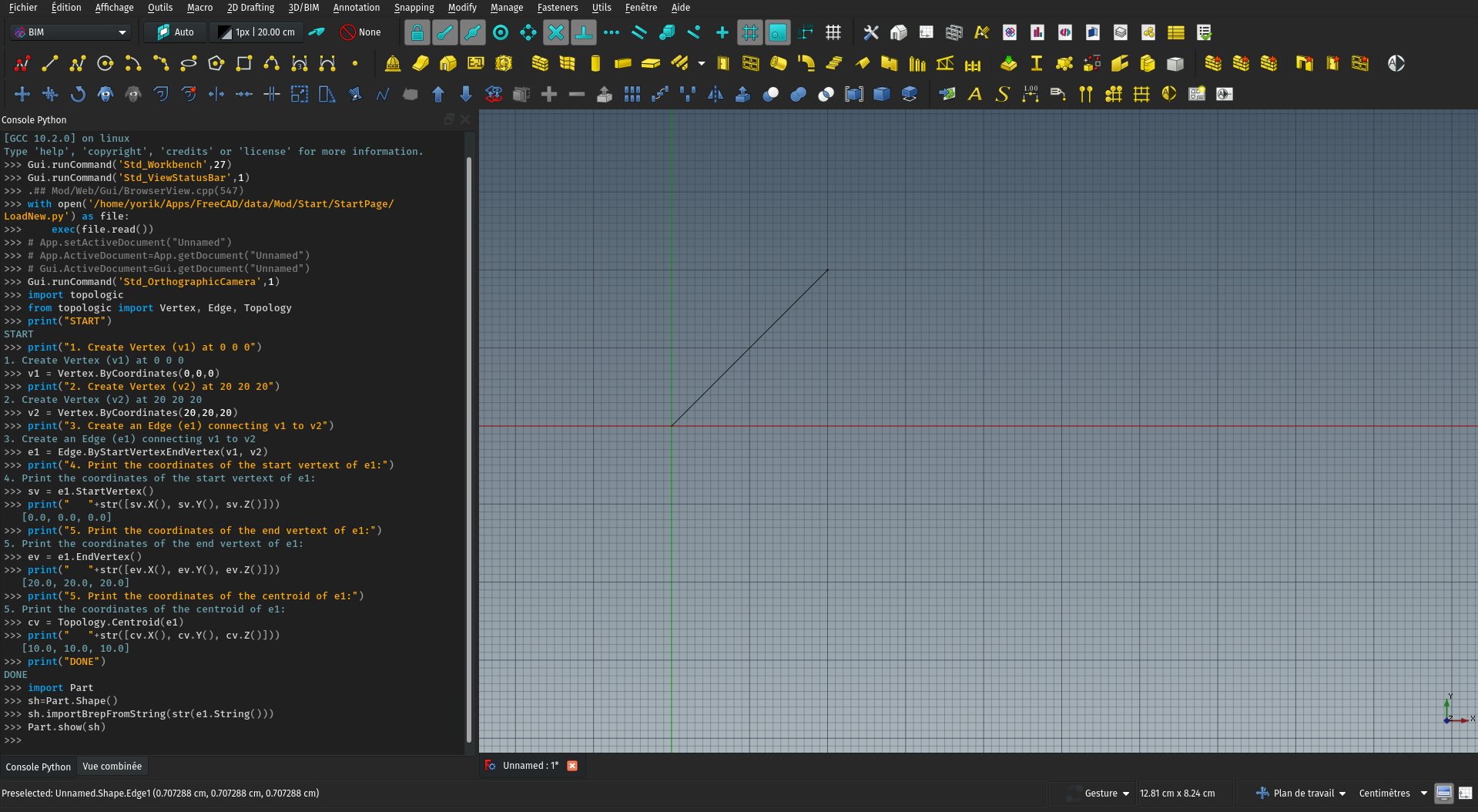
Topologic is a super interesting open-source application that allows to generate space, structures and more complex systems based on rules and relationships. It has other uses too such as providing an interface for energy analysis. With Topologic, you can study things such as floor/use ratios, distances to travel, or any other relationship, and have your building design driven by these values.
So far, Topologic was available only as a plug-in for some proprietary BIM applications. In the last months, the Topologic developers have done an amazing job at porting it to Python. As a result, it became instantly available to Python-hungry applications such as Blender or FreeCAD.
Furthermore, Topologic uses OpenCasCade under the hood, the same geometry engine as FreeCAD. This turns the geometry produced by Topologic instantly and natively translatable to FreeCAD geometry.
So far none of us has explored much the path of using Topologic inside FreeCAD, but it has already been tested successfully (it works!) and the Topologic people have also gone way forward in integrating it with Blender too. So all the pieces are there to make something cool
As you might know, all the Arch/BIM objects in FreeCAD are already able to use a shape generated by another FreeCAD workbench. I plan to extend this so they become capable to use shapes generated by other software and modules too. That would allow BIM objects, for example, to be made with Topologic or the amazing new native IFC framework of BlenderBIM...
Lots to play with!
Updated translation scripts
The main script has been updated to be much more straightforward to use, and now automatically adds any new language that reaches 25% of translated content. Strings are now updated more or less each week, which allows much better detection of problems.
Do you maintain a FreeCAD external workbench and would like to have it translated? We now have a series of tools and methods (included automation scripts) to do it properly.
Extended text tool
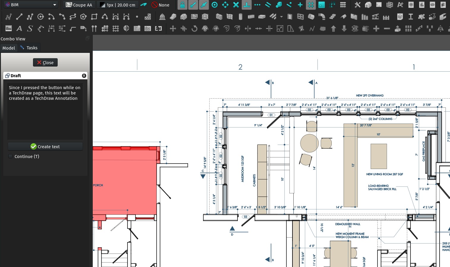
The Text tool found in the BIM workbench, which was before just the original Draft Text tool, has now been extended to also produce a TechDraw Annotation if you use it on a TechDraw page.
Do you find this convenient? Or is it confusing? Tell me!
Arch unit override
The Dimension tool found in Draft and BIM workbenches already allowed you to force a dimension to be displayed in a given unit, no matter the current units settings of your FreeCAD session. It was just not possible to force the use of imperial arch style. Now, you can just use "arch" as a Unit Override, and the problem is solved!
New feature page
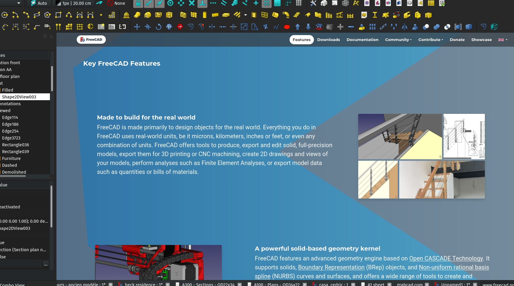
I started a new Features page on the FreeCAD homepage, to better showcase the different powerful features of FreeCAD. To be extended!
Shape2dview autoupdate
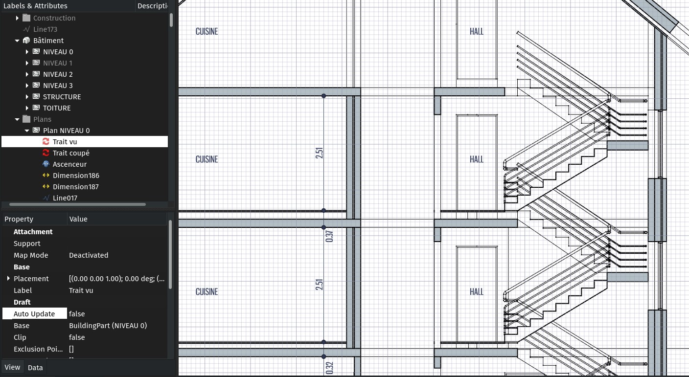
The Shape2DView object also gained an Auto Update property., that works the same way as TechDraw views: If you turn it off, the Shape2Dview is not updated automatically anymore when its source object changes. You need to right-click it and force update.
This allows for much more efficiency when you have many views of a same model in a document.
freecad.org
This is certainly the big news of this year: freecad.org is ours!!! It is not fully connected to the different parts of the FreeCAD web world (wiki, tracker, forum...) yet, but we go step by step to make sure nothing breaks existing links. This happened thanks to the KiCAD people who stepped in and made this possible. This is a huge step in having FreeCAD more recognised as a professional tool. Thanks a million, folks!
There is more to come soon in that area, stay tuned!
Hatch tool
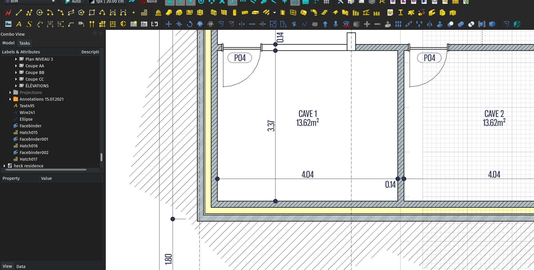
I kept the best (in my opinion) for the end: The Draft and BIM workbenches now have a proper Hatch tool. This still needs some testing, but this is how it works so far:
- You select an existing object containing faces, click the tool, and the faces get filled with a hatch pattern. If the base object changes, so does the hatching.
- It produces a standard Part shape, so it works everywhere (TechDraw, DXF export, booleans,...)
- It uses the TechDraw patterns code. By default it uses the included PAT file of TechDraw, but I would recommend googling for an acad.pat out there and use that instead... The default PAT file in TechDraw preferences will affect both TechDraw and this tool.
- The PAT file used by this tool is recorded in the object, so you can have several objects using different PAT files. Opening that file on a computer without the appropriate PAT files will open fine, but the hatch objects won't be modifiable. The PAT file itself is not included in the saved file.
- The TechDraw system doesn't handle well dashed patterns yet. So for now stick with patterns that have continuous lines (anyone up to trying to solve this?
- The TechDraw algorithm only works well in the XY plane. So the Draft Hatch code translates all faces to the XY plane, calculates the hatch, and moves the hatch back to the face location. This is still buggy sometimes, so there is a Translate property that can be turned off, so it doesn't perform this relocation. If your base faces are in the XY plane, that option can be safely turned off. Here too, if someone wants to help me to look into the relocating bug...
That's it for this month, more to come soon, I swear!
Comment on this post on Twitter Facebook FreeCAD forum Mastodon - Show replies