Categories:
-
3d 96 articles
-
animations 16 articles
-
architecture 47 articles
-
blender 98 articles
-
bédé 19 articles
-
techdrawing 24 articles
-
freecad 193 articles
-
gaming 1 articles
-
idsampa 8 articles
-
inthepress 8 articles
-
linux 57 articles
-
music 1 articles
-
nativeifc 34 articles
-
opensource 270 articles
-
orange 4 articles
-
photo 16 articles
-
projects 35 articles
-
receitas 176 articles
-
saopaulo 18 articles
-
sketches 163 articles
-
talks 25 articles
-
techdrawing 24 articles
-
textes 7 articles
-
trilhas 3 articles
-
urbanoids 1 articles
-
video 47 articles
-
webdesign 7 articles
-
works 151 articles
Archives:
-
2007 22 articles
-
2008 32 articles
-
2009 66 articles
-
2010 74 articles
-
2011 74 articles
-
2012 47 articles
-
2013 31 articles
-
2014 38 articles
-
2015 28 articles
-
2016 36 articles
-
2017 41 articles
-
2018 46 articles
-
2019 59 articles
-
2020 18 articles
-
2021 20 articles
-
2022 7 articles
-
2023 25 articles
-
2024 15 articles
-
2025 3 articles
FreeCAD Arch development news - July 2017
WTF, July development news in August, I hear you yelling (it's not only me!) But there was some last minute topic I really wanted to complete to include in this report... But now that it is complete, I think it deserves another post on its own, so I'll only mention it here briefly. It will be worth it, I swear
First off, I'd like to thank once again everybody who is contributing to my Patreon campaign and through there helping me to spend more time working on FreeCAD. This month I passed over USD 500/month, which becomes pretty important. In Brazil, where I live, the "official" salary of an architect (that is, recommended by the national council of architects) is around USD 2500/month. In reality, only some architects working in public institutions earn that much, in the private sector the usual salary is about half that amount. To put things in context, the 10% bar, that is, the salary you must earn to be in the richest 10% in Brazil is around USD 1100. So my 500/month begin to represent some consequent weight (it's almost a teacher salary). Yeah, these things make you think a LOT about what value is. And for who.
I started this Patreon campaign not really knowing where it would go and if it would allow for something serious, but now I begin to really believe it can change a lot. Working half-time as an architect and half-time as a FreeCAD coder is an idea I'm growing really fond of...
But enough about me, there is quite a lot to tell this month.
Parametric IFC
This is the big thing I wanted to merge before writing this report. I'll post something more detailed soon, but the idea is basically to export all the parameters of FreeCAD objects to IFC. So when reimporting that IFC file in FreeCAD, parametric objects are fully and faithfully restored. The idea is to show/prove that yes, IFC is totally adapted for parametric design. More on that very soon.
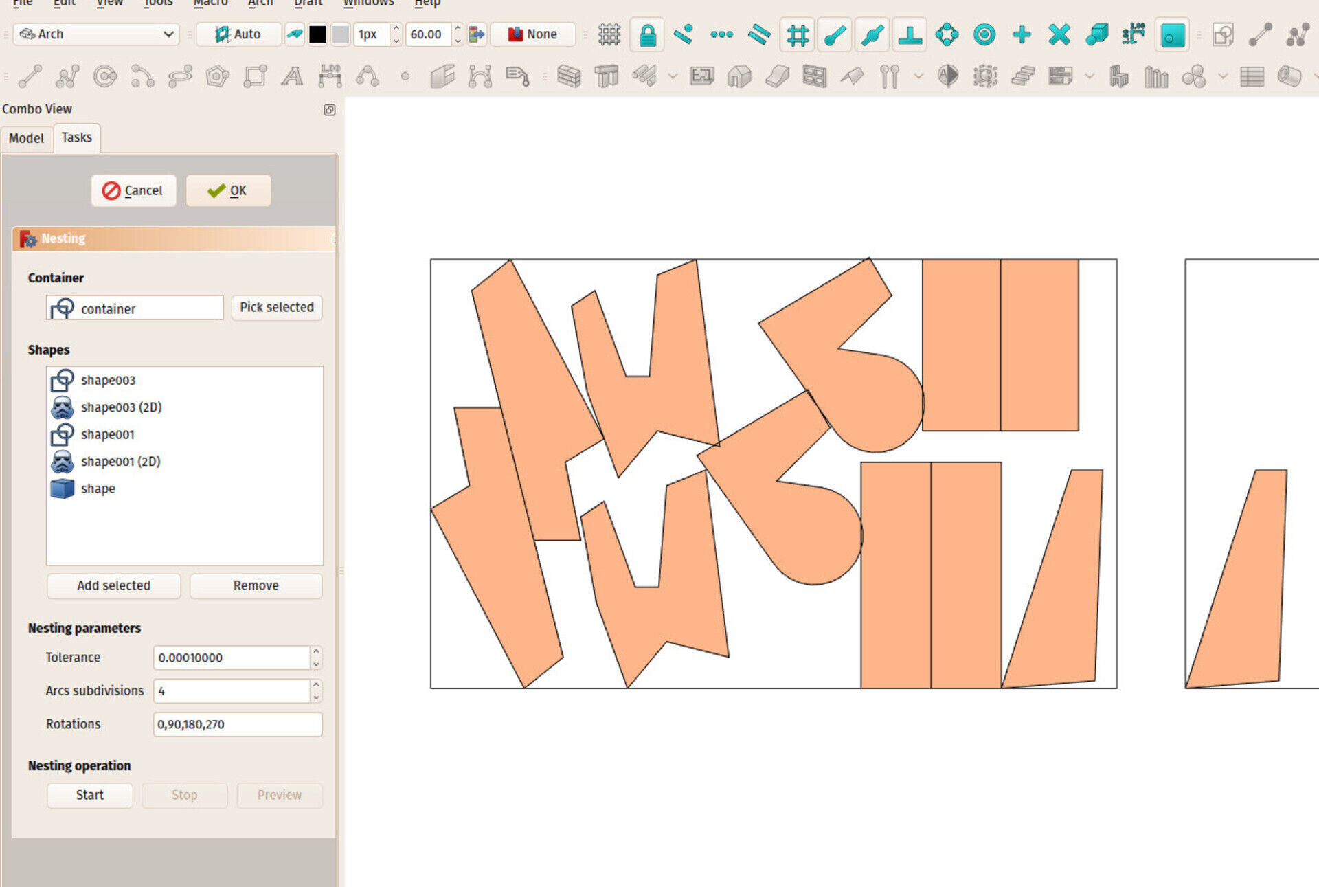
Nester
So the big thing I have been working on these last months is now merged in FreeCAD. I have been posting about it in the previous report already. It is an algorithm that organizes shapes to fit into a containing shape. This is useful in CNC operations, when, for example, you want to cut out a series of wooden pieces out of a wood panel, and want to stack all these pieces the best possible way on your panel.
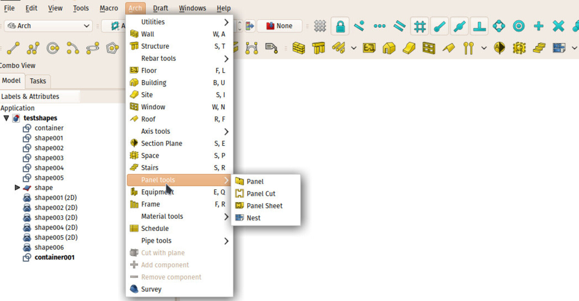
There is now a nesting tool in FreeCAD, located in the Arch workbench, under the panel tools:
The system is simple, you launch the tool, select the containing object, then add the objects to be placed inside. Tune some parameters if needed, and launch the calculation. It is currently not much optimized and quite slow. When the calculation has finished, you can see a preview of the result, and if you apply that result, the object get moved and rotated to their preview position.
The next two features I'll add are support for margins (you usually don't want te pieces to touch, but leave a certain margin between them) and allow for non-rectangular container, so for example you could reuse scrap material easily. Then it'll be time to attack some optimization.
The nesting algorithm itself is separated from the tool above, so it could be used differently by other tools and workbenches. And also, it can be recoded in C++, which should make it run a lot faster. That will be done too later on.
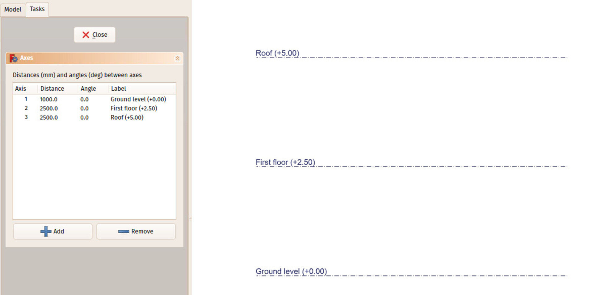
New axis behaviour
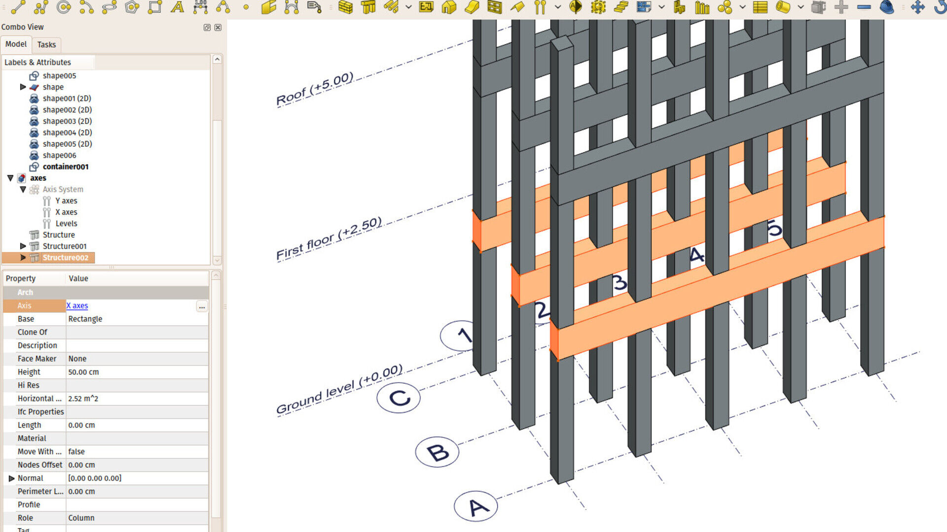
I also introduced several changes to the Arch Axis system. There was already a way to make a series of structural objects spread over the crossing points of different axes, but it was not very easy to find and weird to use. I believe the new system is much cleaner and powerful. It basically works like this now:
- The old Axis System tool is still there, it has simply been renamed
to Axis. It has a
different icon (
 )
and it still does what it did before, that is, it creates a
1-direction series of axes. For example, all the A, B, C axes.
)
and it still does what it did before, that is, it creates a
1-direction series of axes. For example, all the A, B, C axes. - That tool has also gained a couple of extra features: You can now give it a series of labels, one for each axis, that can be displayed next to each axis (you can fine-tune the position). And you can turn the bubble off. This allows to use the axis for many different scenarios, such as indicating levels.
-
There is now a new Arch tool, called Axis System that now really does what the
 icon means: Organize several axes series into one system. It can
take two or three axes objects (you can edit that by double-clicking
the axis system in the tree). Its function is basically to calculate
the intersection points between all the axes.
icon means: Organize several axes series into one system. It can
take two or three axes objects (you can edit that by double-clicking
the axis system in the tree). Its function is basically to calculate
the intersection points between all the axes.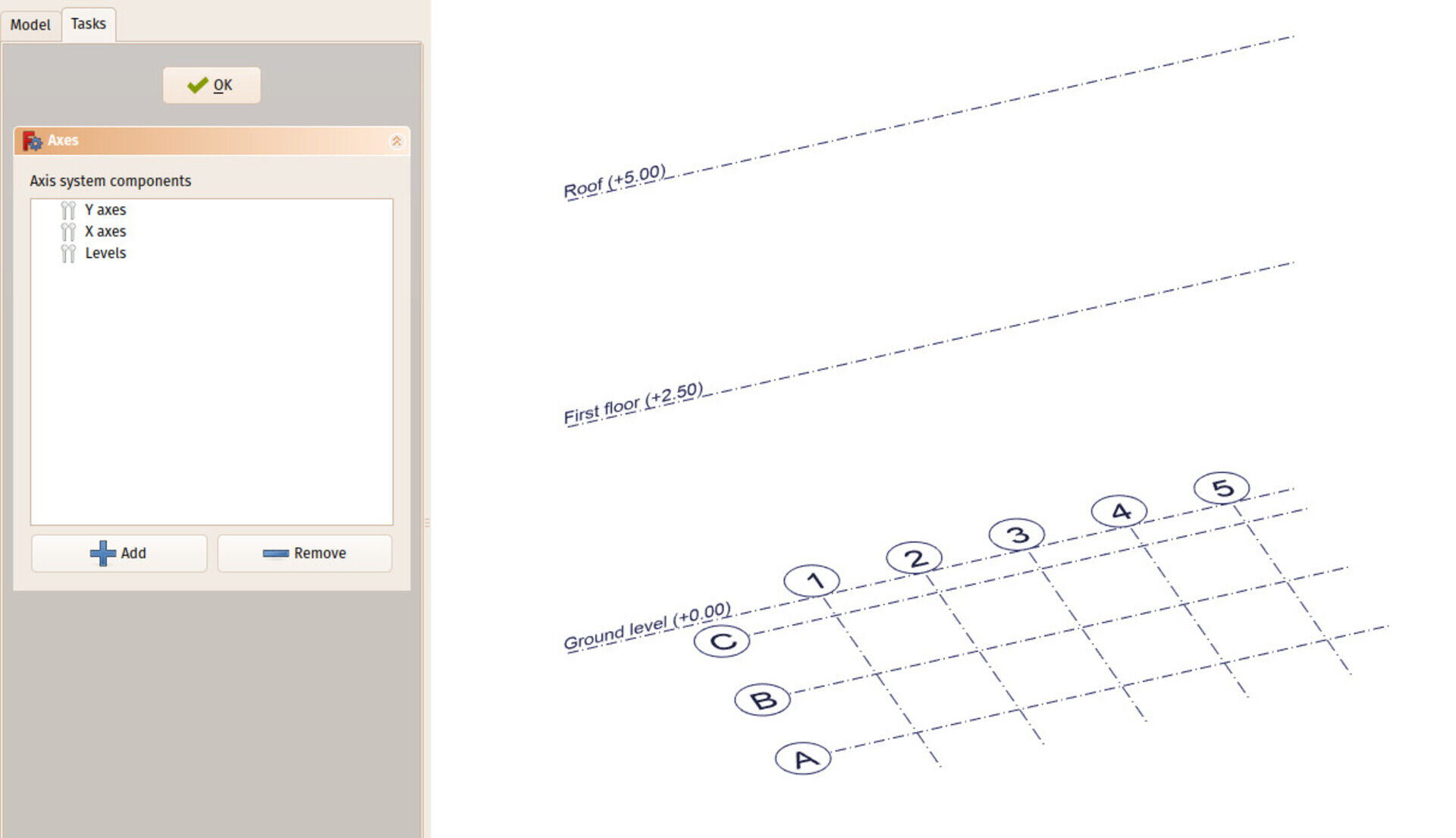
-
Not only structures, but all Arch objets can now be spread along axes or axes systems. For that, they gained a new Axis property. By setting this property, you can make your object be duplicated automatically. The rule is as follows:
- If the Axis property points to an axis system, the object will be duplicated on each intersection point of the axes in the system
- If the Axis property points to a single axis, the object will be duplicated once on each axis
- Otherwise, if the Axis property points to any Shape-based object, the object is duplicated on each vertex of that shape.
Now I think the situation is much cleaner, it's much easier to first create your axis systems properly, then make your other arch objects make use of it, and change/undo all this whenever needed. Also,by using any other shape as an axis system, many wilder possibilities become possible, such as using a sketch to drive the position of Arch objects, etc.
Working Plane Proxy enghancements
The Draft Working Plane tool is something you use constantly and everywhere when working with Arch. It is one of these tools that grew more and more complex over time, and that is now quite a powerful behemoth... For who is not used to Draft/Arch, it is responsible for setting a 2D plane where all the subsequent Draft and Arch operations will take place. The location of this working plane is represented by the Draft grid, that shows the position and orientation of the plane, and also gives a visual interval (the grid size), which you can also snap to.
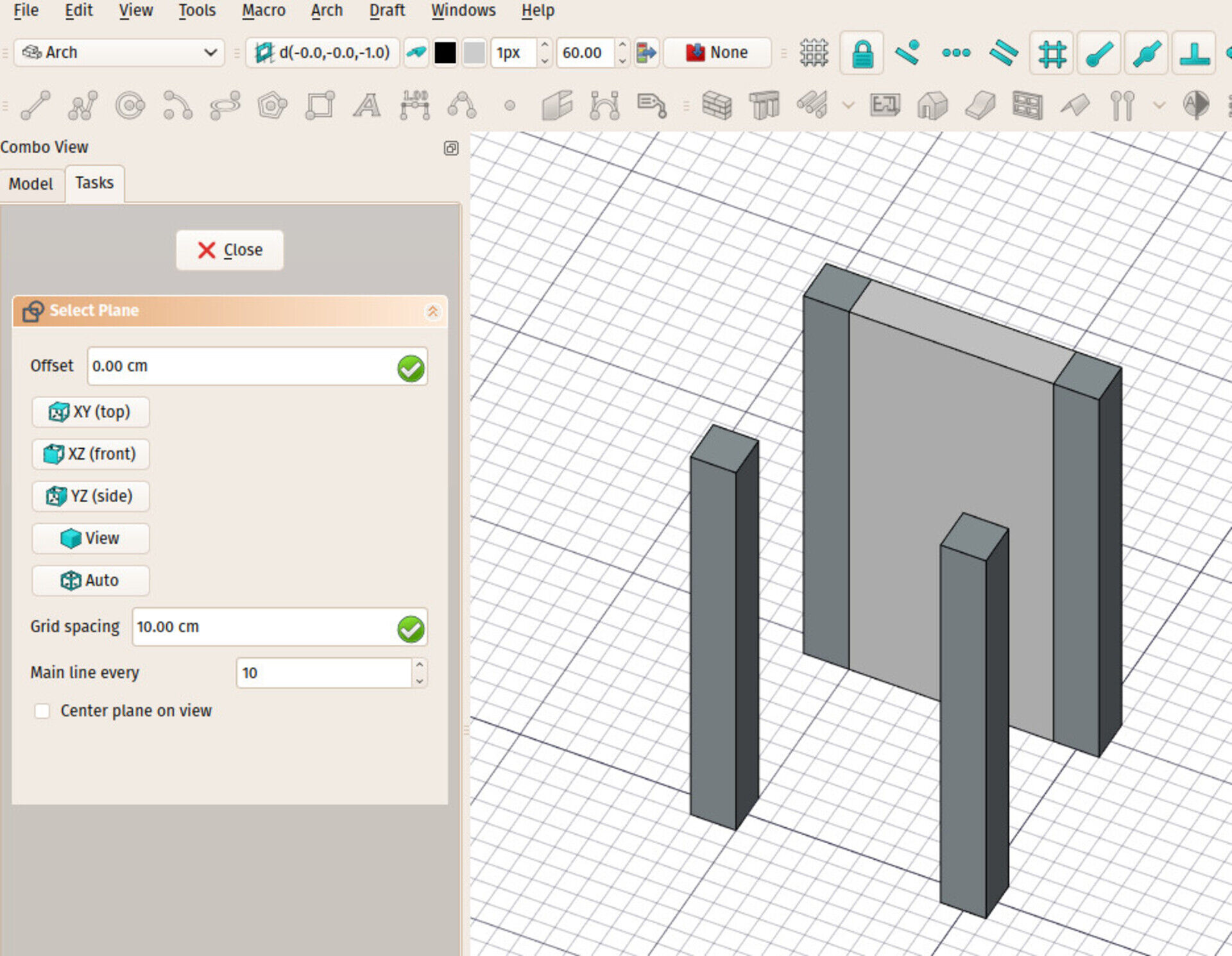
The current possibilities are fair already, you can set that working plane quickly to one of the origin planes (top, front, side) or select a face and make the working plane adopt that face orientation and position.
Now I added a new Working Plane Proxy tool in Draft, that stores the position of the current working plane. It is represented on screen by a small widget (the size is customizable).
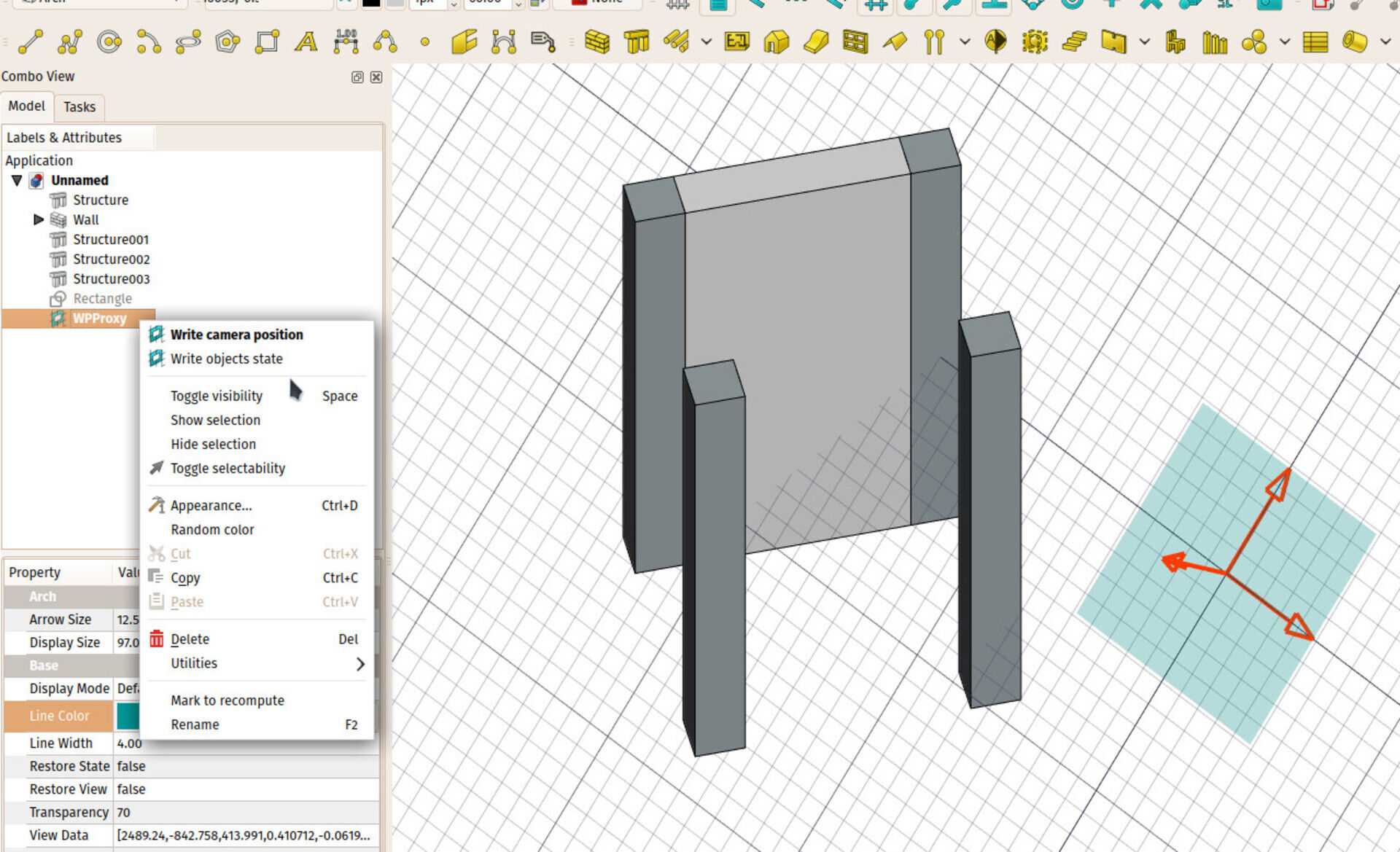
When selecting this widget and pressing the working plane button, the working plane will return to the location/orientation of the widget. You can even move and rotate the widget by conventional ways (it has a Placement).
The idea is that you can now save important working plane positions in your document, precisely, without the need to have "real" geometry there.
This proxy object also has two more interesting features: a Restore View property, that will, when restoring the working plane to the proxy position, also restore the camera position. So you can use the proxy object to store not only the position of the working plane, but also the view angle. You can change/store the current view anytime to a proxy object, by right-clicking it in the tree.
The other feature is a Restore State property that, when restoring the working plane, will also restore the visible/invisible state of all document objects (the ones that were present in the document when storing those states, that is). Here too, you can store the current state anytime by right-clicking the object.
With these two features, we are paving the way for a more conventional BIM environment, where you can switch from working on one floor to another floor, and all your environment (working plane, view orientation, visible objects) will change accordingly.
Next thing I'll look at is how to tie that to Floor objects, but these floors need a good refactoring first...
Rebar / non DAG workaround
The recent GSOC work on Arch rebars (I strongly suggest you to have a look at the impressive work being done by Amritpal, our GSOC student, and several members of the community around, the image above is taken from there) also gave us the opportunity to tackle a long-lasting inherent design problem of the Arch workbench, the famous non-DAG bug. DAG stands for direct acyclic graph. It describes a type of graph or tree which all flows in the same direction, where it is forbidden to go backwards. The relationships between objects in a FreeCAD document is a DAG.
That means the dependency chain between FreeCAD objects must always flow in the same direction: You can object C that depends on object B that depends on object A, but you cannot have object A that depends on object B that in turn depends on object A. That would be a cyclic dependency (you cannot know which one comes first, A or B) and is forbidden in FreeCAD (if you find yourself in such a situation, FreeCAD will print non-DAG error messages and refuse to process anythingmore until you fix the problem).
Two Arch objects were constantly creating non-DAG situations: Windows and Rebars. The window, for example, often depends on its host wall (in order to know on which face it lies) and the wall also depends on the window to know how to drill the opening where the window is placed. The workarounds I had imagined until now to circumvent the problem were really not very satisfactory (for example create a second wall, so the base wall and the wall with the opening were two different objects).
With the Rebar, we now experimented a new idea that seems to solve the problem for good. It is not the "parent" object that knows which "children" it holds anymore. It is the child that knows which "parent" it belongs to, and the parent is not dependent on the child anymore.
That introduces a bit more complex system: The wall doesn't know which window is part of itself anymore, so when updating its geometry, it now has to "scan" the scene to find the windows it must use to drill openings. But this is a very ponctual and unperceptible slowdown, and I think totally worth the much cleaner situation and the vanishing of the dreaded non-DAG problem.
The Rebar object already uses the new system, and it seems to work very well, so I'll adapt the window to use the same system in the coming days.
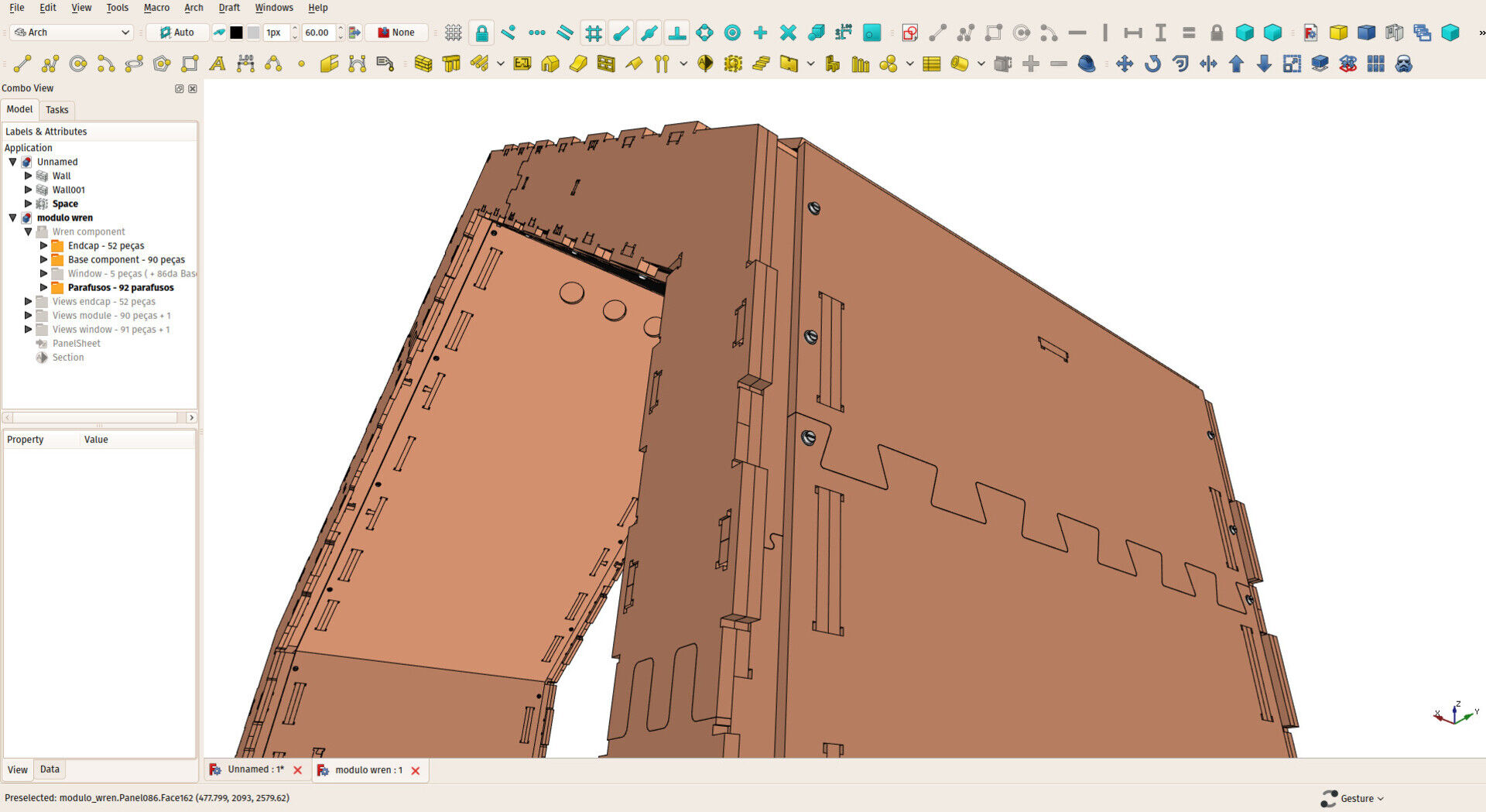
Cabinet design
Another talk I had with a FreeCAD user (that will soon become a more stucturated plan) lead me to this interesting experiment, where you take a simple Part Box, and use it as a "driver" shape for inner objects, like the panels and doors of a cupboard. This is an interesting workflow, and I liked to be able to work with simple boxes, that contain their own more detailed components.
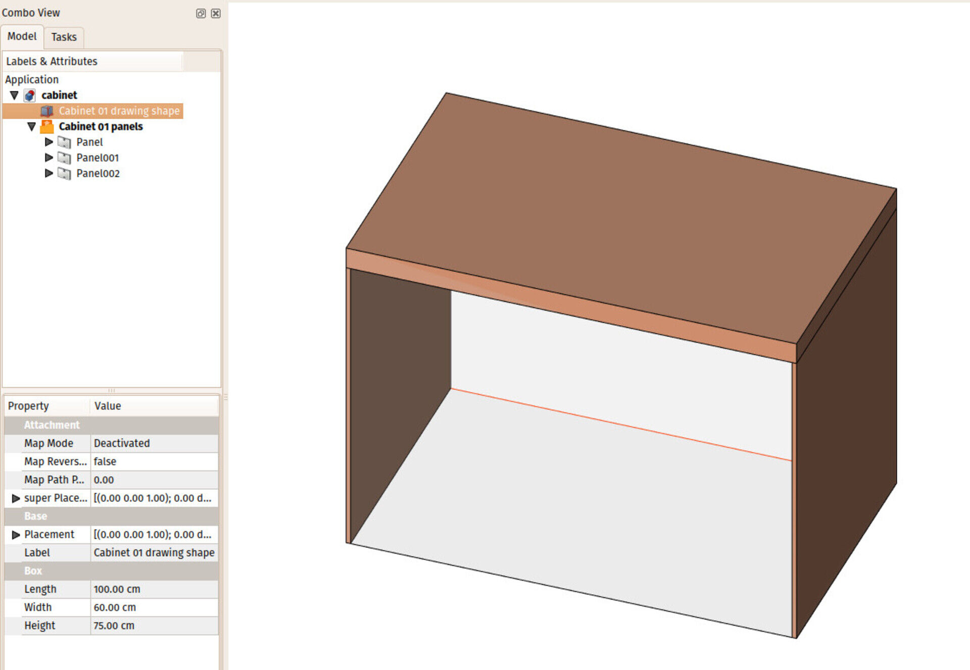
The test file is here if you want to have a look at how it works.
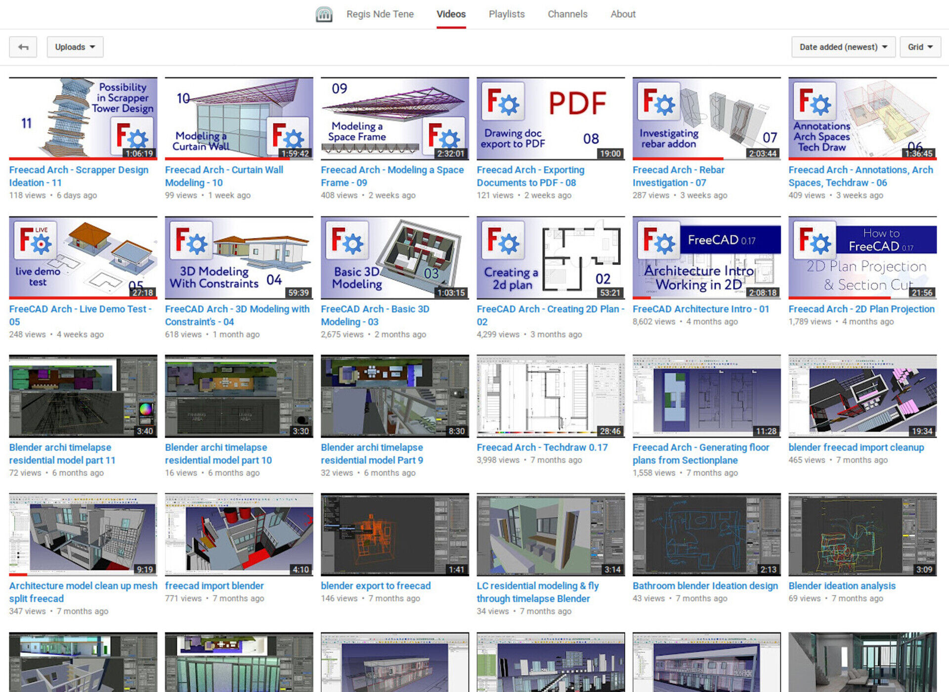
I already had other discussions before about furniture/cabinet design with Regis and others, it would be a good time to think about a proper workbench for it.
Talking about Regis, one of the most knowledgeable Arch/BIM FreeCAD users around, have a look at the impressive series of videos he has been producing lately about BIM work in FreeCAD...
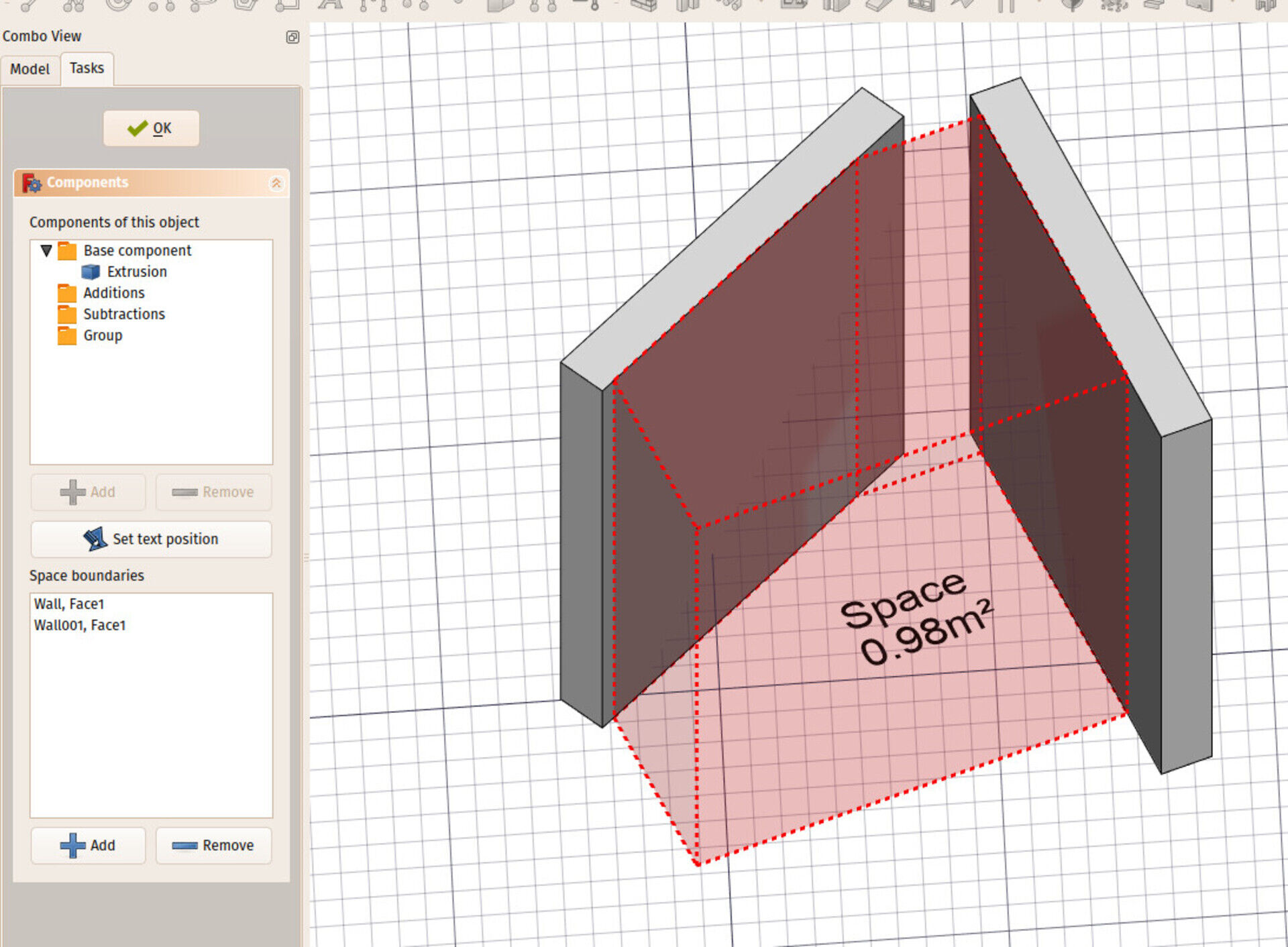
Arch space bounds
I also added UI controls to edit the boundary objects of Arch Spaces. Spaces can be based on a solid object (their shape is therefore the shape of the solid object), or a set of boundary faces (the shape of the space is therefore the bounding box of all these faces, subtracted by the volumes - or half-spaces - behind those faces), or a mix of both (the shape of the space is the shape of the base solid, subtracted by the half-spaces behind the boundary faces).
There was until now no way to edit the list of boundary faces without using the python console, this is now solved.
That's it for now, sorry about posting late! Still a lot that I wanted to do this month that will be for the next month, but step by step we're getting there. Thanks for reading, thanks to everybody who help me to make this come true, and as always, comments are welcome!