FreeCAD Arch development news - August 2017

Time for our monthly development report, explaining a bit of what I did this month. Thanks again to everybody who help me on Patreon, each month we're getting higher! If you don't know about it yet, you can help me to spend more time working on FreeCAD by sponsoring me with any amount you want on Patreon. Some of you have asked me if it was possible to give me some money directly via PayPal, well it sure is! My PP email is yorik (at) uncreated (dot) net.

Bugfixing

This month however I will have much fewer to share than usual. There are two main reasons to this, one is that I've been doing a lot of bugfixing, which is too boring to talk about here. It is boring to do too, of course. Any coder will tell you that it is much more fun to develop new features than fix bugs. However, they are very important. The stability of an application depends heavily of the relentless testing, identifying and fixing of bugs.

I saw where FreeCAD comes from, and when you compare it with FreeCAD as it is today, even with all the remaining bugs and problems it has, the evolution of its stability has been phenomenal. All thanks to this: tiny bugfix after tiny bugfix...

There is a story I always like to tell about bugs. We architects are usually very sensitive about errors. Doing a mistake is a terrible thing for an architect, and results in huge blame, shame, guilt. You always try to show that you know everything. As you can imagine, this also comes with a strong tendency to hide the dirt under the carpet.

When I began to work with Jürgen and Werner on FreeCAD, it is one of the first things that surprised me much: How these guys treated their own errors as a normal thing, a bug. Bugs happen. You are human, you make mistakes, the same way as you breathe or eat. It wouldn't make sense to feel guilty for this. Since then, I always try to treat architecture work like that too: Consider your mistakes as a normal part of what you produce, try to make them appear (unit tests for architecture?) so they can be processed and fixed.

Jürgen and Werner and all other FreeCAD developers, if you guys read this, thanks! I am learning a lot with all of you.

Draft Scale UI

One of the things I did that was really sorely needed is a better User Interface for the Draft tool, that was really clumsy (you needed to "indicate" graphically the scale factor). Now there is a simple, proper dialog to scale things up/down, which allows you also to choose the result: Scale the original objects or produce a Draft Clone (where the scale can be changed later).

WikiLab

The other reason why this report will be less interesting this month is that the construction of our WikiLab project has started yesterday, so I simply had less time to work on new FreeCAD stuff. There has been quite a lot of work to do these last weeks to have all the construction documents ready before construction start, and the approval process ended up not being as smooth as we thought either (it is actually not entirely finished...).

But all this is also not work for nothing. The main issue with approval is, as you might imagine, fire resistence. Our WikiLab is made of wood, which burns. The risk for human beings is extremely low (the room is very small, only holds a few people, is escaped very easily, nobody will sleep there, etc), and the OSB panels we are using already have a slower buring rate because the glue they are made with acts as a fire retardant, but the problem is that there is as of today very little official record of all this. People in charge of approval basically want to see a document that guarantees them that such wall will hold a certain time under fire. These documents don't exist yet, because people rarely build walls with OSB panels, so panels manufacturers have little interes to pay for the research and fire tests needed to obtain such guarantees. Plus, these tests are very specific, so in our case a fire test would be valid only if it was made with the exact same wall composition as we are using.

This is a well-known problem when using experimental systems. Convincing authorities is very hard. But that is also where this process is interesting and useful, when done, we will have created a precedent, which will lower the difficulty for all subsequent ones, because they'll be able to refer to this one.

Coin-based views

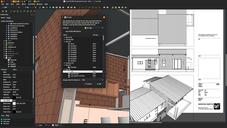
The work on the WikiLab construction documents also allowed me to play further with another idea I had: The 3D view of FreeCAD is pretty nice: It is anti-aliased, line style, width, thickness, color, transparency are configurable by object, it has a nice support for fonts, and even things like transparent textures. So instead of the heavy ans slow workflow needed to produce "traditional" 2D views with the Drawing or TechDraw workbenches, you could simply grab a nice view of your 3D window.

So far these cannot be exported "as is" to vectorial 2D. Exporting a 3D view to PDF is supported by the Coin3D engine (which powers the 3D view of FreeCAD), but the result is often buggy, the engine struggles at rendering some complex 3D situations to PDF.

However, exporting a 3D view to bitmap formats usually works very well. Most architects who will read this might dismay in horror at the idea of exporting architecture work as a non-vectorial format, but there are many "but" here.

First, it makes sense of course to export your work in a CAD format, such as DXF or DWG if others need to work with it. But a PDF? Will anyone ever import a PDF to work on it in a CAD program? That would be pure masochism, there wouldn't be much you could do with it. Also, when working in an open-source way, or any case where your base files are more easily acessible to others, and are in an open format, all this discussion looses a lot of its meaning... If a person can get a FreeCAD file, why would that person need a PDF file

The next advantage of a vector-based format such as PDF is the reduced filesize. However, this is true for basic line-based work, but as soon as you use more fancy things such as transparency or textures or gradients, most CAD systems will turn that into bitmap anyway, so much for the file size. And large complex areas filled with one color can often be smaller in size in bitmap than vector format, where havy triangulation is needed (which by the way often stays visible in the PDF file). So there is not much difference at the end.

The third advantage of vector-based files is that you can zoom in and things continue to look sharp (this is certainly only useful for on-screen viewing, has any of you ever printed a PDF file at higher scale than 1x?). But this is just a matter of resolution, just save an image with enough resolution to be well readable when zoomed a lot, and this problem disappears. Plus, even if your image is embedded in a PDF file, zomming is blind-fast compared to zooming vector-based PDF files.

In the last years I've used bitmap files more and more to show traditional CAD work like floor plans. You can do all kinds of fancy things in Photoshop Gimp, and if you manage your layers well, it is totally manageable to reimport a layer from your CAD/BIM app when something changes in the project.

So I used this a lot in these construction documents. By using Working Plane Proxies you can easily configure views that you can recall anytime, so it is easy to produce a new image that is identical of the last one when the project has changed. And the Tools->Save image dialog of FreeCAD allows you to save an image with a very high resolution, which gives a very sharp result.

There are sill issues to solve, such as calculating the resulting scale, or ensuring that texts and dimensions have coherent and consequent size across different views, but that shouldn't be hard to solve.

Of course this is not the holy grail. There is still a series of situations where you'll need vector-based output. But when you try to show a project in different ways, like we did here, it might become a lot more convenient.

Arch Grid

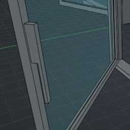
The only real new feature I've been working on this month is the Arch Grid, that I just merged. A tool to construct a grid object, like you do in a spreadsheet: define columns and rows, change their sizes, and merge cells together.

This object can then be used to perform a series of other operations with Arch objects, for example spread objects on its vertices, face centers or edge midpoints, or use it as a base for windows, instead of a sketch, or for any other kind of situation such as constructing railings.

Download that test file here (you might need to wait a bit, because I just committed the change)

That's it for this month I'm afraid, sorry I couldn't do more, next month will likely be like this one too as we will be building the WikiLab, but you can count on me to share all I can during the construction. Almost all our wooden part are cut and ready to be assembled, the masonry base is being built now, and the assembly is scheduled to start on september 12th. If you are in São Paulo at that moment, don't miss the opportunity to participate!

Thanks again to everybody who is helping this adventure to come true, each month a step closer to a full, feature-rich open-source BIM application!