Categories:
-
3d 96 articles
-
animations 16 articles
-
architecture 47 articles
-
blender 98 articles
-
bédé 19 articles
-
techdrawing 24 articles
-
freecad 189 articles
-
gaming 1 articles
-
idsampa 8 articles
-
inthepress 8 articles
-
linux 57 articles
-
music 1 articles
-
nativeifc 30 articles
-
opensource 266 articles
-
orange 4 articles
-
photo 16 articles
-
projects 35 articles
-
receitas 176 articles
-
saopaulo 18 articles
-
sketches 163 articles
-
talks 25 articles
-
techdrawing 24 articles
-
textes 7 articles
-
trilhas 3 articles
-
urbanoids 1 articles
-
video 47 articles
-
webdesign 7 articles
-
works 151 articles
Archives:
-
2007 22 articles
-
2008 32 articles
-
2009 66 articles
-
2010 74 articles
-
2011 74 articles
-
2012 47 articles
-
2013 31 articles
-
2014 38 articles
-
2015 28 articles
-
2016 36 articles
-
2017 41 articles
-
2018 46 articles
-
2019 59 articles
-
2020 18 articles
-
2021 20 articles
-
2022 7 articles
-
2023 25 articles
-
2024 14 articles
FreeCAD BIM development news - May 2018
Hi there,
Time for a new update on BIM development in FreeCAD. Since last month saw the release of version 0.17, we now have our hands free to start working again on new features! There is quite a lot of new stuff this month, as usual now, spread between the Arch and BIM workbenches. For who didn't see the previous posts where I explained the idea, I am now basically more and more trying to split BIM stuff between what goes into the Arch module, which is included into the FreeCAD source code, which will contain all the "hard-core" stuff (object definitions) and will probably grow more and more deprecated as a workbench, and the BIM workbench, which will contain all the UI (User Interface) work.
This split has many advantages, mainly 1) to make it easier for other people to contribute to BIM development without the need to dig into the FreeCAD source code, and 2) be easier to experiment, outside of the FreeCAD source code itself.
For the FreeCAD user, these distinctions don't really matter, you should basically now use the BIM workbench, and everything from Arch will be there too.
As always, the time I can spend on FreeCAD is a diret consequence of the help I receive from many of you on Patreon or LiberaPay. Thanks a million to everybody who is contributing already, and if you aren't, what about joining the family? Also, helping me with a couple of bucks is just one way to help. Python coding is easy, and the Arch/BIM split makes it even easier to get into it. There is a forum thread dedicated to BIM development. All the help is welcome!
Also: Some pleasant things can happen while you work with FreeCAD...
The video
This month, the video is about windows. Hope you'll like!
Arch Panel waves
This is an item that was annoying me since a long time and has now gained a good update. Panels were already able to be displayed as a flat plate, or as a corrugated panel. But the system was very slow, because a small curve section was generated, then copied over, then extruded, then unioned to the next curve section, resulting in a lot of boolean operations, which, in any CAD system, are an expensive operation that you as a developer must try to use as little as possible.
Besides, that system didn't do a very good job with multilayer panels, and couldn't have a different bottom face, which is both common in sandwich panels and convenient when you don't need to show the curves on the bottom face.
Both these issues are now solved. Now, internally, the code generates one big profile for the whole panel, which is then extruded and doesn't need to be unioned anymore, which makes it way faster to calculate. Additionally, there is one more wave type ("spike"), and you can make the bottom face flat.
Beam drawing mode
This is another long-time request, it is the ability to "draw" beams directly in the 3D view, like walls. So now, when pressing the Structure button, you have an option to switch to that beam drawing mode, instead of just placing an element. I'm not too happy about that interface yet, it seems annoying to me to have to click that control to switch modes, but it is more important to have the tool to work well first, sooner or later an idea will arise to make the UI workflow better.
Another related idea I am always toying with, is if it wouldn't be more interesting to split the "internal" functionality offered by the different BIM tools into separate toolbar buttons, in other words, less complex tools, more toolbar buttons. For example, instead of one Window button that has 6 window presets, have 6 window buttons, each running a different preset. I have no clear idea about that yet, I am not convinced that it is an interesting trade-off, it seems to me it's only moving the compexity to another place...
More thinking is needed there
Draft scale reference mode
The Draft Scale tool, when I coded it, was very remotely molded upon the AutoCAD scale tool. One feature I used a lot in AutoCAD was reference scaling. You take one distance, and you say "I want this distance to become that other distance". But this made the Draft Scale tool horribly clumsy to use, specially with 3D objects. In fact, nobody was using it and people were using the Clone tool, which allows to set a scaling factor in an easy and intuitive way like (2.0, 2.0, 2.0) for scale factors on the X, Y and Z axes.
So a while ago I remolded the Scale tool to have the same, simple system. Now you choose your objects, set the scale factor, and choose if the result is a Clone object, or if the original objects must be modified directly (this doesn't work for all object types ATM).
Now we finally have the best of both worlds: The scale tool still works the simple, reliable way, but you can also define the scaling ratio by picking a reference distance and a target distance in the 3D view. The scale factor will be the ratio between these two distances.
All objects can have all IFC types
This is a very simple change, but that open large possibilities. All Arch objects already had a "Role" property that could be used to fine-tune the use of each object, for example a Structure could have its Role set as Beam, Column, Slab, etc.. But this was basically not used anywhere, except when exporting to IFC. And each Arch object type has its specific list of possible roles.
Now the Role property has been renamed to IfcRole (this is part of a larger effort I am beginning, to group all Ifc-related properties into some specific group), and it can take any IfcProduct role. The IfcProduct is the master class of all "physical" (and a couple of non-physical ones too) elements found in a building, such as column, wall, door, etc (full list here).
In other words, from now on, any Arch object (or, in fact, any FreeCAD object, as you can just encapsulate it in a Component) can be exported to any IFC type. This is something surprisingly simple, offered by very simple apps like Sketchup, but that is curiously hard to do in many BIM applications...
Draft Text object
The Draft Text tool, until now, was using a basic App::Annotation object, which was not very handy to use and lacked a couple of features. Now the tool is using its own python object, which is much more comfortable to work with. The two immediate results is that the text object now has a placement, so it can be rotated and placed in any custom position you may want, and it is now a common scene node, so it won't appear through other objects anymore, like the old object did.
From python, you can use Draft.convertDraftTexts() to convert old-style Draft texts in a document to the new format.
BIM IFC elements manager
A new "manager" tool is now functional in the BIM workbench: The IFC elements manager. What it does is basically shows you all the Arch objects of your document, together with their IFC role. Here you can easily manage all these roles individually or several at once, and make sure everything will export as you want. That screen also allows you to rename objects.
Better window placement
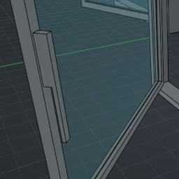
Accurate window placement has always been a pain in FreeCAD. So much that me and others ended up advising to disable snapping when placing windows, then reenable it and move the window to its correct position. Hopefully, thanks to a very simple change, this is history.
Now, when placing a window, when hovering with the mouse over a face, the window will take and keep the orientation of that face, until you hover on another face. This allows to both align a window to a face, and take advantage of the full snapping tools, for example to place a window on an edge or a vertex, like one would expect.
This is not yet 100% perfect, one would still like to be able to place a window at a certain position relatively to another element, but this is a larger question that relates to other elements too like walls or columns. In any case it is already a good step forward, now the window tool finally works properly.
Flatten wire option
It can happen, when working with Draft Wires,that the wire is not exactly flat. Nothing in FreeCAD or OpenCasCade prevents that. But it might not be usable to form a flat face anymore. This is specially often the case with geometry that you import from other applications, where rounding could occur. The DraftGeomUtils module already had a flattenWire() function that would project all the points of the wire onto its median plane. Now, a right-click context menu option has been added to Draft Wires to perform that action, so it has become a piece of cake to fix those problems.
New AutoCAD-like prompt
This is only an experiment so far.
It is a recurrent request from new FreeCAD users coming from AutoCAD: They want an AutoCAD command line. I don't like the idea, basically because it conflicts with a shortcut-based UI like FreeCAD has. If you look at how other apps with both shortcut-based UIs and command line do, for example QCAD or LibreCAD, it doesn't work really well. At some point the app needs to decide if the L key you pressed is a shortcut or the first letter of a command line command. You need either to move your mouse over the command window, or press SPACE to "switch" to command-line mode, which kills a bit the efficiency of it all.
But I have this idea that it would be possible to "fake" the system, and offer the user not a "real" command-line system, but a keyboard-only workflow with the same speed and easiness of the famous AutoCAD command line. To make it simple, pressing the keys would still trigger shortcuts and UI actions, but you would get a "feedback" of it in the output window of FreeCAD, making it look exactly as if you were typing stuff in it.
So far two Draft tools have been adapted to that system, as a proof of concept: Line and Wire. There are a couple of improvements to bring to the console, like the possibility to show stuff in bold font, or maybe enable clickable links, I will look at that later on. But I am not convinced yet if this is usful at all. After all, it is totally possible to pilot most of Draft and Arch commands via keyboard only since a long time...
Please test and give your opinion! There is a forum thread dedicated to this topic.
Material layer presets
The Multimaterial dialog already allowed you to define different material layers, to be used by walls, panels, and windows. In the case of windows, it was a bit clumsy to use, you had to create one material layer for each window component. So if you had 20 panels in a window, you needed 20 material layers too. And take care that it uses the same name.
Now instead of a layer name in the Multimaterial editor, you can also click the drop-down arrow and select a window component type. That material layer will then apply to all window components of that type. So you now just need to create a Multimaterial with one material as "Frame" and another as "Glass panel", apply it to all your windows, and you are done.
BIM Views manager
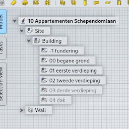
Another new widget is available in the BIM workbench: A Views manager, that will open inside your Combo View. It is basically a small widow that will list all the Draft WorkingPlane Proxies of your document. You often need to double-click them to set the corresponding view, but they are often buried deep down your model tree. Now they can always be conveniently be available there, no more endless scrolling!
Later on, as the BuildingPart object evolves and can also define a view, it will also appear in that view.
TechDraw DXF export
Finally, this is not mine but the result of the hard work of Wandererfan, the TechDraw master, and of huge importance to Arch/BIM users, TechDraw pages can now be exported to DXF. Every single TechDraw feature is not 100% supported yet, but Wandererfan is working amazingly fast on this, and it is very usable already. The result is a very clean and compact DXF file.
If you haven't tried to use TechDraw for Arch/BIM work yet, give it a try, it is still a bit slow for production use, but most of the needed features are there already, no doubt we are getting very close!
That's it for this month, thanks for reading, thanks for the support, more to come next month, don't forget, if you are new to these pages, I can go faster with your support!