Categories:
-
3d 96 articles
-
animations 16 articles
-
architecture 47 articles
-
blender 98 articles
-
bédé 19 articles
-
techdrawing 24 articles
-
freecad 190 articles
-
gaming 1 articles
-
idsampa 8 articles
-
inthepress 8 articles
-
linux 57 articles
-
music 1 articles
-
nativeifc 31 articles
-
opensource 267 articles
-
orange 4 articles
-
photo 16 articles
-
projects 35 articles
-
receitas 176 articles
-
saopaulo 18 articles
-
sketches 163 articles
-
talks 25 articles
-
techdrawing 24 articles
-
textes 7 articles
-
trilhas 3 articles
-
urbanoids 1 articles
-
video 47 articles
-
webdesign 7 articles
-
works 151 articles
Archives:
-
2007 22 articles
-
2008 32 articles
-
2009 66 articles
-
2010 74 articles
-
2011 74 articles
-
2012 47 articles
-
2013 31 articles
-
2014 38 articles
-
2015 28 articles
-
2016 36 articles
-
2017 41 articles
-
2018 46 articles
-
2019 59 articles
-
2020 18 articles
-
2021 20 articles
-
2022 7 articles
-
2023 25 articles
-
2024 15 articles
FreeCAD BIM development news - August 2018
Hi there,
One month passes bloody fast, doesn't it? So here we are again, for one more report about what I've been coding this month in FreeCAD. Looking at the text below (I'm writing this intro after I wrote the contents) I think we actually have an interesting set of new features.
None of this open-source BIM journey would be possible without the help of everybody who contributes to my Patreon or Liberapay campaigns, and therefore allow me to spend a good amount of working hours per month on FreeCAD. Thanks a million to all of you, it is really making a difference for FreeCAD, we're well on our way to a good, open-source BIM application.
The house illustrated in this post is a famous house built by architect Vilanova Artigas in São Paulo and was modelled by Wilson Melo.
So let's have a look at this month's features, but first, here goes our monthly video:
The video: 2D drawing
In FreeCAD, like in most other BIM applications, many 3D objects are based on 2D objects: Walls are based on a line, columns and beams on a 2D profile, etc. In most cases, you are not forced to draw that 2D object yourself: You can draw a wall directly in the 3D view, or you can place a structural component by selecting a preset profile from a list. However, all these objects can also be made from a custom 2D object that you draw yourself. There are many ways to do that in FreeCAD, this video will give you a quick overview of the available options.
Ideastorming
As announced last month, we are reaching the first goal I have defined on Patreon, which is, a place where we can discuss BIM ideas and features to be implemented in FreeCAD, and you guys can vote for them, and I would do my best to implement the most voted ones. I had a look at the different (open-source and not) solutions available to do that efficiently, but unfortunately the results of this search are not very good. Most "feature voting" applications are very old and unmaintained, or require a heavy web infrastructure to be put in place, and you will certainly agree that our time should be spent better than in maintaining heavy web infrastructures just for that purpose...
So I thought, why not simply use the Github issues system? It is possible to vote there, submit new ideas, etc. Most open-source projects hosted on Github use it. It might not be the ideal (given the fact that Github is now owned by Microsoft, etc..) but at least it's easy to use, anybody can add new ideas, vote for existing issues (give it a "thumbs up"), etc.
I am starting to put some ideas on the BIM workbench Github page, have a look there under the "issues" tab, I'll add more in the coming weeks. Don't hesitate to add your own ideas there, or comment as much as you like on the existing ones.
Full groups hierarchy in IFC
I discovered a small but bright IFC trick recently that might not be "proper" IFC behaviour, but that is definitely improving our FreeCAD workflow a lot: Groups, in IFC, are handled by an object called IfcGroup. However, groups are not really part of the standard way to use IFC, which is to use spatial structures (Buildings, Storeys, Spaces, etc..). As far as I could see, they are just offered as an additional way to create relationships between objects, if anyone really wants to. You will rarely see an IFC file that contains groups. Revit and ArchiCAD, although both offer the functionality, don't use groups much.
In FreeCAD, however, groups are a very important feature. All the objects of your model are appearing in the tree view, so it is very important to organize them. Grouping is an extremely powerful way to organize your model, and, unlike other methods such as using storeys or layers, it is completely free from any "meaning". You, the user, decide how you want to organize your model. Will you group all your walls under a "Walls" group? will you make sub-groups for different types of walls? Will you not use the materials system at all, and instead group all your objects by material? The model is yours, the choice is yours. Also, every project is different, it makes little sense to force users into one kind of arrangement. An office tower model should definitely not be organized the same way as a house.
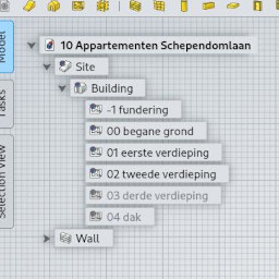
In FreeCAD, you can mix everything together: Have groups inside levels (which are now handled by the BuildingPart object), levels inside groups, groups of buildings, anything your wild imagination (or very concrete requirements) dictates. But this was all lost when exporting to IFC.
Now I discovered that IfcGroups are actually derived from the same base entity as other IFC grouping features such as Storeys or Buildings, and, as such, they share some functionality. More important, it is possible to stack groups as part of these other entity types.
So from now on, you can export your wild model structure to IFC, re-import it, it will come back exactly as it was. Most of our BIM competing applications might still not be able to cope with such a complex model structure, poor them, but hopefully they will do their homework at some point.
Forgive me for the quite exaggerated last sentence, but I couldn't resist
IfcElementAssembly support
Another IFC feature I've implemented in the last month, is support for IfcElementAssembly, which is the standard IFC way to define an element made of several other building elements. For example a truss system, or a bathroom unit. It is a bit like grouping, with the difference that the assembly is not just a group but a real, physical, manipulable object.
In FreeCAD, any BIM object can be an assembly of any kind of geometry or other BIM objects. You just need to add them to its "Additions" property. However, until now, if the host object was a wall, it will be exported as a wall.
Now, if you change the Ifc Role of any BIM object to Element Assembly, it will be exported as such. But even better, BuildingParts will also be exported as IfcElementAssembly when its Ifc Role is set as such. And it is much easier to add objects to a BuildingPart, as you can drag/drop objects into it in the tree view, and is a much more "intuitive" way to construct an assembly.
When importing an IFC file containing IfcElementAssembly entities, they will be rendered as a BuildingPart, so all their components will be available and manipulable.
On our way to a full roundtrippable IFC <-> FreeCAD workflow!
Quantities
Finally we now have preliminary support for quantities. I say preliminary, although it works well already, because I'm still not sure about the future direction of this.
Basically, the IFC format supports defining objects by quantities. Together with the geometry of an object, for example a wall, you can also attach quantities to it, for example a height value of 3 meters, or a thickness value of 20 cm. This is all arbitrary, you can decide yourself what name you will give to these quantities (it it "thickness" or "width"? "largeur" maybe? or "??"?) and, even more problematic, you can make them lie (the "thickness" value you give is not the same thickness as the geometry you provide).
So it is complicated to trust these values. However, the point is not there. The idea is that an application that doesn't have geometry support, for example a spreadsheet application, would be able to open an IFC file and build a list of quantities of all the elements in the file, without the need to have very complex geometry tools to extract that information from the geometry.
The idea is brilliant of course. Imagine "opening" your IFC model in Excel?
So here is how it works in FreeCAD now. The IFC Elements Manager (sorry, the documentation is not there yet at the time of writing, will work on it in the coming days) of the BIM workbench now has gained a new tab that shows available quantities for BIM objects. So far, I only considered objects that had standard, universally recognizable quantities such as width or length. This will be developed further along the way.
For any of them, you can now mark if you want those quantities to be exported to IFC. That screen will also show a warning sign when such a value is zero, which probably indicate a problem somewhere that you should look at before exporting.
These quantities are then exported to IFC and attached to the corresponding object. When reading back an IFC file, the quantities are not read, as we prefer to get them from the geometry, which is more trustworthy. In the future, we could think of comparing what the geometry says with the given quantities (FreeCAD as a lie detector for IFC files?), but I can't think of much use for that.
Start center redesign
I had been busy with this for some time, and it's finally ready. The old start page, which appeared when you opened FreeCAD, was something a bit clumsy and not very usable nor interesting. Now we have something that is much more useful, both for newcomers and experienced users. There are three tabs, one for your files, one for documentation, and one to have a quick peek at the recent activity in the FreeCAD world (latest changes to the source code and latest posts on the forum), which is a feature many users liked in the previous version.
All of this is customizable, translatable and themable, and you can even replace the start page by any HTML file of your own. That can be useful for example in companies or schools so they can display additional content.
There is also a "notes" area, that you can enable in the Start preferences, where you can write text that is saved across FreeCAD sessions. This could be useful as a kind of "FreeCAD to-do list".
There are still some small hiccups depending on the platform, but we'll address them on the way. Don't be scared about the colors in the images above, I adapted the start page colors to my desktop theme (you can do that in Edit->Preferences->Start), but by default it looks like this:
New website
This was not done by me but by FreeCAD user AR795, with the help of many others, bu have you seen the gorgeous new FreeCAD website? Next we'll adapt the rest of the FreeCAD web universe (wiki, etc..) to the same aspect.
BIM Box tool
Until now, the BIM workbench featured, among its 3D tools, the standard Part Box tool. Using boxes is very practical in BIM, more than half of the geometry we create is usually made of these rectangular shapes, and the Part Box is a very simple and versatile tool that has 101 utilities. The way it is created, however, is often annoying: A 10mm x 10mm x 10mm box appears at the origin point when pressing the button, which requires several additional operations to move it to the correct location and set its length, width and height dimensions. Most of the time I was using a Draft Rectangle that I then extruded, which was faster.
Now I rescued an existing macro and turned it into a full new BIM Box command (sorry, no doc yet) command, that still creates a Part Box, but graphically in the 3D view. You give two points to define the base line (length), a third point to define the width, and a fourth to define the height. You can also enter length, width and height manually in the Task panel, but you still need to click the two first points to define the position and orientation of your box.
These boxes can be used as walls (just press the wall button with one selected), beams, columns or any other BIM object, or as a subtraction to any of them (select the box, CTRL+ select the host object, press the Remove button).
Section plane controls
The Section Plane tool has also gained a series of improvements. First, when you create one, if you have objects selected, for example a building, the section plane will automatically be placed at the center point of the building and resized to encompass it.
Then, by double-clicking the section plane to enter its edit mode, you now have several controls to flip it in other directions and resize it to fit. So it is now much easier and faster to create multiple views and sections.
Section plane caching
With Wandererfan, we are working on having proper support for Section Planes in TechDraw, which is the FreeCAD workbench used to produce ready-to-print sheets. At the moment, you must still use the TechDraw ArchView tool, which is the only one that supports Section Planes. However, that tool has many limitations, because it produces its view through SVG, and therefore looses many of the TechDraw features such as the ability to add hatches and dimensions.
But while proper support is not ready, I already experimented with caching. The contents of the TechDraw ArchView is now cached, and only recalculated if the objects seen by the section plane change. So you can now move, rescale, change thicknesses, etc... of ArchViews without redoing the heavyweight calculations, which makes it much faster.
This seems to work pretty well, so that might be a good idea to implement further in TechDraw later on.
Terrain macro
Finally, I built this little macro the other day that builds a whole Site object out of a series of contour lines, that you can for example import from a DXF file. Your contour lines can be organized in any way you want, grouped in different layers, and don't need to be connected into wires (they can be a series of simple lines). The macro solves it all.
Internally, it breaks everything into separate edges, re-joins everything into wires, turns the wires into b-splines, sorts them by elevation, then builds ruled surfaces between the contours, then builds a shell object out of the surfaces. Finally, that shell is used as the Terrain property of a site.
There will be many situations where it won't work correctly (for example the sorting by elevation will produce wrong results if there is more than one contour with a certain elevation), which we can adjust later on, until it is good enough to become a real FreeCAD tool.
But the results are quite good already, and of a much better quality than the point cloud-based method I used some time ago. Plus, it is easily editable by editing the b-splines.
That's it for this month, see you in September!