FreeCAD BIM development news - July 2019

A house in FreeCAD

Hi Everybody,

Time for a new edition of our monthly reports about BIM development for FreeCAD. I've been quite busy with work this month, but there is still a good quantity of cool new features to show.

Once again, a big thank you to everybody who helps this effort by donating to my Patreon, Liberapay or Paypal accounts. On the advice of Liberapay people, we have now set up an official Liberapay team page for FreeCAD. All FreeCAD developers (or other community members who do significant work on FreeCAD) who have a Liberapay account will be added there, and any money received through that page will be split equally between them. If you are donating to me personally but would prefer your donation to go through that page instead, please don't hesitate. I'll be happy either way.

Apologies for not having a video this month, I didn't have time to make one and likely won't have this week, and I thought best not to delay this report any longer. Next month we're back with the videos!

So let's not loiter any more (whatever that means), and go to the juicy part:

Lightweight mode for Arch Reference

Which is real and which is fake?

As you know if you've been following this column, we already have in FreeCAD's Arch workbench a tool called Arch Reference that works like AutoCAD's Xrefs or Revit's Links: It allows you to include the contents of one file into another, while keeping the content in the first file. So if you change the first file, the second one gets updated automatically.

In FreeCAD, this works using a very simple mechanism: All Part-based objects, which include all Arch/BIM objects, when saved inside the .FCStd file, also have their shape stored as a .brep file (OpenCasCade's native format). This allows FreeCAD to not need to recompute the shape of these objects when opening the file, saving precious time.

The Arch Reference does just that too: When referencing (or linking) another file, it reads the .brep objects stored inside the file. So it doesn't need to recompute the objects. When you have large assemblies of objects "packed" into one, for example using Compounds or BuildingParts, this makes a huge difference, the Reference object only needing to read one single brep file.

Last month, I implemented one new mode for Arch References, called "Lightweight". You'll find it in the "Mode" property of the Reference object. So far it only works if you are referencing a Building Part from another file.

The lightweight mode works like this: Building Parts, when saved into a .FCStd file, will together with the brep file also write their full Inventor node, that is, their visual representation in the 3D view, which is a much lighter, mesh-based geometry than the full brep shape, which is NURBS-based.

When in Lightweight mode, Reference objects will load that saved Inventor file and add it to the 3D view, giving you a perfect illusion that the object is there. However, it is not fully there, many operations won't work because there is no real shape behind it, so no way to perform calculations. But if you just need to see the other objects, not interact with them, this can work very well.

Unfortunately, I was hoping to get a huge performance gain, compared to the normal, brep-based system, but it turns out to be not much faster, as far as I tested. However, there is much room for optimization (for example, the openInventor also has a binary format, which should be much faster, there are many ways to compact the nodes, which should yield huge speed gains in the 3D view, etc)

In any case it works well so far, have a try!

BIM Views improvements

The BIM views dialog

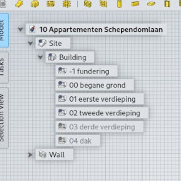
The new BIM Views tool that we introduced last month has gained a bit more polish, you can now do several building part-related operations directly from it, such as isolating a level, saving the current view orientation, etc.

Dynamic materials icon

Colored material icons

Following the test I did with layers last month, Arch materials now also have a dynamically colored icon in the tree view, that shows the material color. I used a caching mechanism, to avoid having to redraw the icon each time the tree requests the icon, and this still causes minor issues, such as the icon not being immediately redrawn when you change the color, but we'll fix that along the way.

Multimaterial improvements

Multimaterial editor

There was quite some time I wanted to give a bit of work to the Arch MultiMaterial tool, and here are several improvements that have been added:

  • A button to invert multimaterials: Click the button, and the materials layers stack will be inverted, top to bottom.
  • Support for negative thicknesses: If you give a material layer a negative value, this layer won't be drawn in the object. This is useful, for example, to represent an air gap in a wall. In the future, when we'll have walls able to contain studs and structure, this will be useful to not fill a certain layer with material.
  • The total thickness, made from the sum of the material layers, is now shown on the MultiMaterial task panel. (It considers negative thicknesses as positive, of course )
  • Misc visual improvements: buttons have icons, and the column widths are remembered across sessions.

View clipping for Building Parts

A clipped level

Building Parts are now able to clip the 3D view, like Arch SectionPlanes do: You can define an offset between the Building Part's base plane, which is given by its Placement, and a cut plane. By default, that cut plane is situated 150cm above the base plane, which would be more or less the eye level of a person standing on the base plane (you can change that to anything you want). When clipping is activated, everything in the current view above that cut plane is hidden. There is also an "AutoClip" mode that turns clipping on automatically when activating the Building Part.

This brings the workflow with Building Parts much closer to what you do in other BIM applications, where, when switching to a plan view, your plan view looks the way it's going to look on the sheet, that is, with everything above a certain plane cut off.

By combining different options of Building Planes, such as clipping and storing a top view, you can now achieve the same thing: double-click it in the BIM Views window, and find yourself in top view, with everything above its cut plane hidden. Most tools work pretty well in that mode, I'll take care of the remaining ones (windows mostly) in the next weeks.

Big refactor of multi-view grids and working planes

Grids appearing in different views

If you used to work in Arch/Draft/BIM with multiple models open in a same FreeCAD session, you know the problem: the grid would quickly start to go crazy when switching between the views. The grid system has been refactored and I think it works pretty well now.

I'll take the opportunity to reexplain an important concept: The grid, that you see in the 3D view, reflects the current working plane, but it is not the working plane. Each opened 3D view has its own grid. But there is only one, FreeCAD-wide, working plane. If you set the working plane to the XY ground plane, this will count in all opened 3D views.

If you leave the working plane in "auto" mode, however, when switching from one 3D view to the other, the working plane will follow and adapt to the view you are currently in. So we can actually have, as we say in french, both the butter and the money from the butter

Allow to reorder materials alphabetically

Option to reorder materials

This is a minor fix, but it already improves things a bit. By right-clicking the materials group in the tree, you can now reorder its contents alphabetically. This is while we don't have better reordering sytems in the tree view...

Offline Rendering Utils module improvements

This module, that I described last month, is used to help producing files while running FreeCAD without its GUI. I added several new functions to that tool, to retrieve the full GUI object properties from a file (not only the colors), add shadows (see below), and read/write OpenInventor .iv files.

Solar diagram fixes

a solar diagram in FreeCAD

The solar diagram functionality of Arch Sites was a bit buggy, mostly due to the switch to the Python3 version of PySolar, which powers it. This is now solved, and several utility functions have been added for future use, such as retrieving a given sun position for a given site at a given time/date, etc.

Also, the Py3 version of PySolar now works in local time. Since I didn't find a good Python library that can give a time zone from a geographic position (and we don't want to force users to go online everytime), currently the Arch Site has gained a new "Time Zone" property that you must set yourself to get a correct solar diagram. Certainly at some point we'll be able to do that automatically.

Schedule tool improvements

The new schedule tool dialog

In last months video, we showcased two methods to extract quantities from a BIM model, one using the Arch Schedule tool, another using the Reporting add-on. This made me think the Arch Schedule tool was not that bad, although it is not as powerful as the Reporting tool, its syntax is easier, so it is also useful. And, as always in the open-source world, two different solutions for a same problem is not a bad thing. It's a good thing! So I ended up adding a series of improvements to the schedule tool:

  • UI polish: Better and more complete tooltips, icons everywhere
  • Grammar improvements in filters: Before, you had only a couple of predefined filters: Name, label, type, and that was basically it. Now, any object property can become a filter. So you can for example grab all the windows with a certain tag.
  • Export to Markdown: You could already export the results as a .csv file, you can now also export it to a nice markdown table. Cool to place on github!
  • Detailed output: You can now show the results of the schedule as before, each line of the schedule produces one line in the result sheet, or as detailed output, where each object caught by the filter produce one line, and then a total line is added below. This is good for checking that everything is there, however as your model changes, the lines that show the totals might shift up or down, which is not good if you are referencing the cells, for example in a spreadsheet application.
  • Schedules now work without spreadsheet: The schedule tool used to produce an attached spreadsheet, where the results are shown. However, the spreadsheet is slow to update and can make all your model work slower. You can now turn the spreadsheet output off (and delete the existing one if any), the schedule will still work, print its results in the Report view, and still be exportable to csv and markdown. By right-clicking the schedule object in the tree, you can also open a spreadsheet only when you need it.
  • Schedule panel as stan-alone dialog: The schedule tool's task panel was really not practical at all: Too horizontal for the limited space of the task panel. So now it is not a task panel anymore, it is a floating dialog. It will also remember its dimensions when you close it, for next time you reopen it (I'm beginning to use this everywhere...). This is now way much comfortable to work with, and after all, you barely need to look at your 3D view when working on a schedule...

Shadows in the FreeCAD 3D view

Shadows appearing in the FreeCAD 3D view

Another very cool thing I have been toying with for some time, is shadows. In architecture work, shadows are very important. Not only it helps people (and yourself!) to understand the masses, voids and volumes better, but it is also important to take the sun position into account when designing. So viewing the shadows that the sun projects on your model is a very important feature.

Luckily, the coin3D engine, that powers the FreeCAD 3D view, is natively capable of projecting and displaying shadows. Coin3D although quite old and not much maintained anymore, is an amazing piece of software, with very advanced capabilities for its old age. For example, it also has GLSL support, which could allow for things like ambient occlusion or specular bloom in FreeCAD...

With some help from Werner, we managed to set up a system to have shadows enabled directly in the FreeCAD view. It works amazingly well so far, there is still a bit more testing needed to catch all possible issues, but this will soon be consolidated into a real FreeCAD feature.

In the meantime, you can already test with a little bit of python...

Blender's 3D view

Talking about shadows, ambient occlusion, bloom, you might not have heard about this, but the new Blender 2.80 is out, and it is a real game-changer... Check this video by Blender guru Andrew Price to get an idea.

And since now FreeCAD is using Python3 on most platforms, it's time to pack our FreeCAD importer for Blender as an official Blender addon!

That's it for this one I guess, thanks for reading, and see you next month!