Categories:
-
3d 96 articles
-
animations 16 articles
-
architecture 47 articles
-
blender 98 articles
-
bédé 19 articles
-
techdrawing 24 articles
-
freecad 190 articles
-
gaming 1 articles
-
idsampa 8 articles
-
inthepress 8 articles
-
linux 57 articles
-
music 1 articles
-
nativeifc 31 articles
-
opensource 267 articles
-
orange 4 articles
-
photo 16 articles
-
projects 35 articles
-
receitas 176 articles
-
saopaulo 18 articles
-
sketches 163 articles
-
talks 25 articles
-
techdrawing 24 articles
-
textes 7 articles
-
trilhas 3 articles
-
urbanoids 1 articles
-
video 47 articles
-
webdesign 7 articles
-
works 151 articles
Archives:
-
2007 22 articles
-
2008 32 articles
-
2009 66 articles
-
2010 74 articles
-
2011 74 articles
-
2012 47 articles
-
2013 31 articles
-
2014 38 articles
-
2015 28 articles
-
2016 36 articles
-
2017 41 articles
-
2018 46 articles
-
2019 59 articles
-
2020 18 articles
-
2021 20 articles
-
2022 7 articles
-
2023 25 articles
-
2024 15 articles
FreeCAD BIM development news - June 2020
Hi all,
One more monthly development report over the BIM tools for FreeCAD. Not many topics this month, because I concentrated on a couple of larger subjects, but there is pretty cool stuff anyway, read below!
Thanks once more to everybody who contributes to my Patreon or Liberapay campaigns, it really makes a big difference in the time I can dedicate to FreeCAD! We are slowly on our way to make it easier for companies to donate to FreeCAD and get larger donations too, so this kind of effort might soon spread onto other areas of FreeCAD and, who knows, get a lot more of groundwork done!
App Parts, App Links, window types and stub for families
As you probably already know, FreeCAD doesn't have the same concept of families or types, like you find in mainstream BIM applications like Revit or ArchiCAD. However, the system we use in FreeCAD, which is actually similar of how it happens in Blender or even in IFC, is much broader. Basically, several objects can share the same geometry and even, in the case of FreeCAD, other properties as well.
This makes it already totally possible to work with types/families in FreeCAD. For example, you can elect one window to be the family, and other windows to simply be clones of this base window (that you can even place in a "Families" group, to find it easily later on and have all your family definitions conveniently grouped). But you are not forced to, you can perfectly well work without that concept, and consider all windows sharing the same geometry to be equal, without the need to have one "model".
In other BIM apps, the families/types system is often over-constraining. In Revit, you more than often end up having to "model in place", which creates an object that doesn't really fit in the families system, and has completely different behaviours. The limitations of the system are right there.
The traditional way to create clones in FreeCAD is by using Draft Clones, or, if you are using Arch/BIM objects, they have the built-in ability to be a clone of any other (by setting their CloneOf property). Additional properties values can be shared easily between clones too, using expressions.
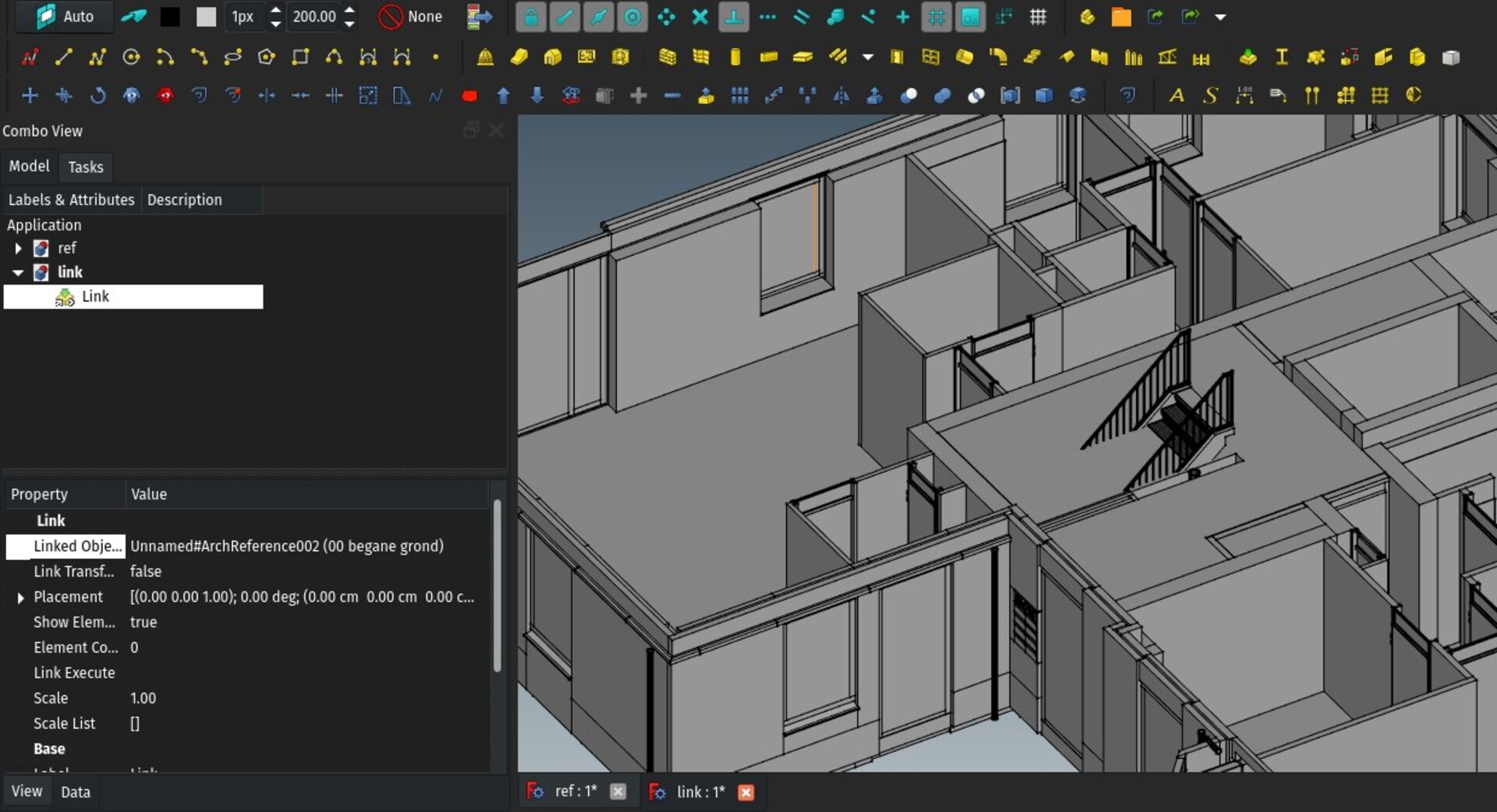
With the introduction of the App Link object in FreeCAD 0.19, we now have a brand-new, more powerful, FreeCAD-wide way to have several objects share their geometry. So the probable future path is that the clone functionality will be deprecated and replaced with App Links, once it can be used 100% in place of the current clones system.
App Links are lightweight copies of an object, with all their properties. The shape is stored only once, and both the link and the base object share their visualisation data. This makes it behave much much faster, as the shape building operation and the meshing + building of the visualisation data is done only once for both. In the case of clones, the second part had to be done again.
App Links also have several other goodies, they automatically share other properties, icon, etc. They are even designed to have their original object in another file or even on a network location such as the internet, but this has not be used yet.
In fact, the only property that can be set differently between a Link and its base object is the placement. It also has a scaling property so the link can have a different scale than its base object.
I have begun experimenting with using App Links instead of clones, and so far the results are pretty good and seamless. Have a try for yourself. This month I adapted the windowing system so an App Link of an Arch Window behaves like a window (it creates holes in its host wall, etc), most other Arch objects work even more seamlessly, and in Draft most tools are also being adapted to work with links.
My roadmap, once we have tested that App Links can be used everywhere in place of clones, is to adapt IFC import/export to support it fully, then prepare a system to automatically migrate files with clones to App Links. Then I think we can retire the clones system and make the clone tool produce App Links instead.
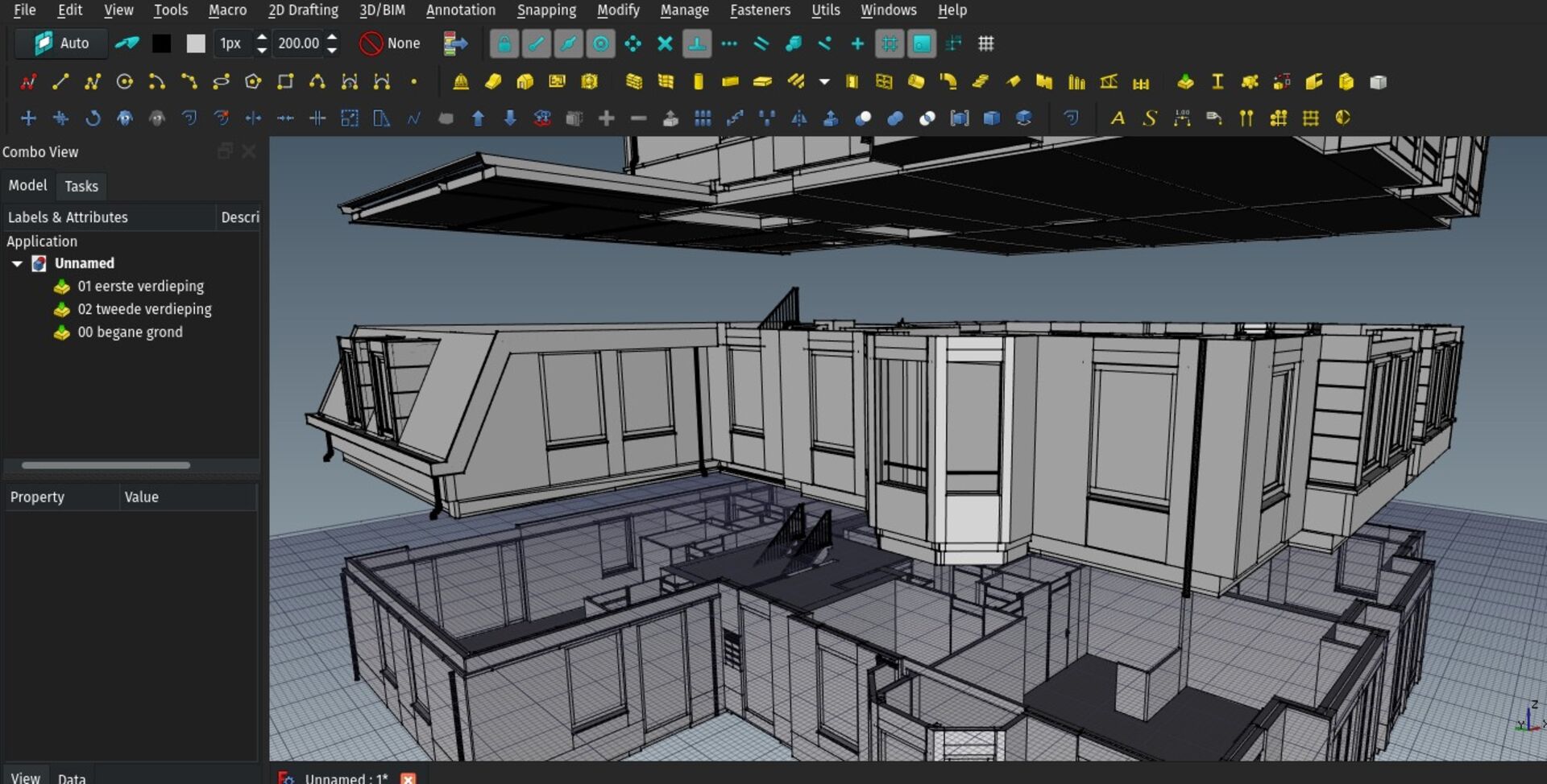
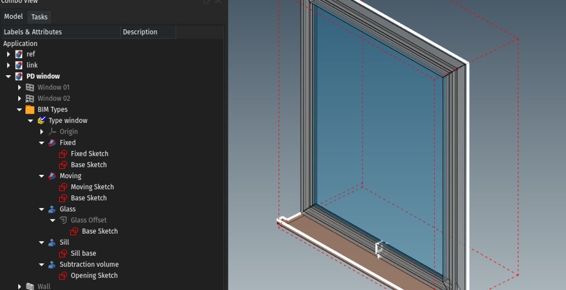
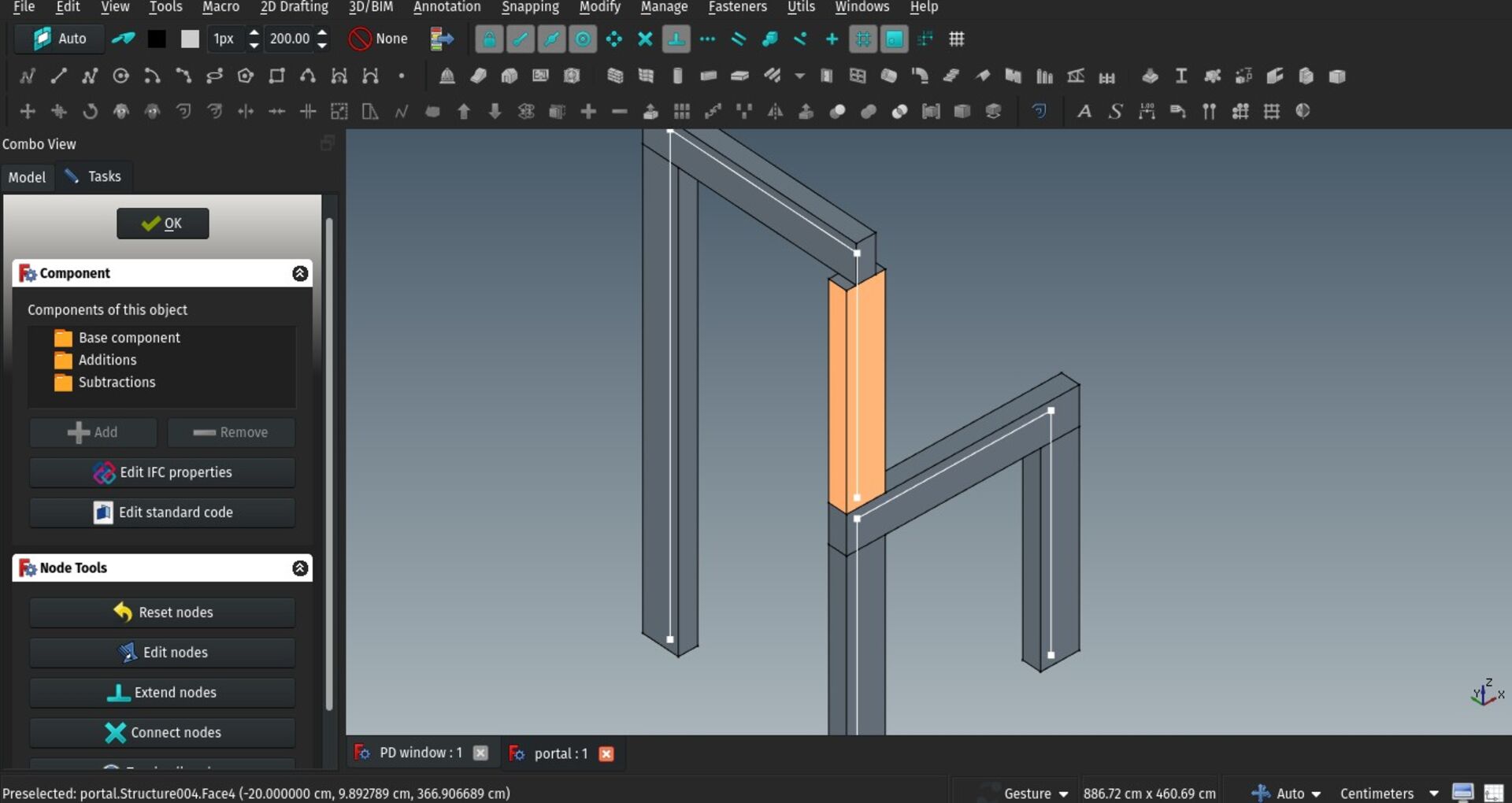
Another feature I've been working on and implementing after seeing Carlo's experiments form last month, is the ability to create windows with Part or PartDesign instead of using the Window tool. This allows for pretty complex and very parametric window definitions, work with master sketches and profile sketches, etc. I built a simple example file that demonstrates how that all works.
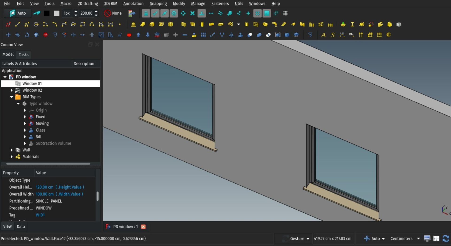
Basically you create an App Part (or Body if you are working with PartDesign), construct your window inside, and add Height, Width, Tag and Subvolume custom properties to your App Part (using properties editor actions) and use this App Part as the base object of your windows. The whole process is explained better in the Window documentation.
You can then elect your App Part as a "window definition", or family, make it as complex as you need, and then either create several windows from the same App Part, or create one and then subsequent App Links from the same window.
I think this begins to give us a pretty powerful families system. We'll extend this system to other Arch/BIM objects as well, although the ability to build a type/family with Part/PartDesign tools is of less importance for other types.
The beauty of it is also that you can make very complex windows with tenths of subparts without making your model tree very heavy, as it is used only once.
Export of wall axes to IFC
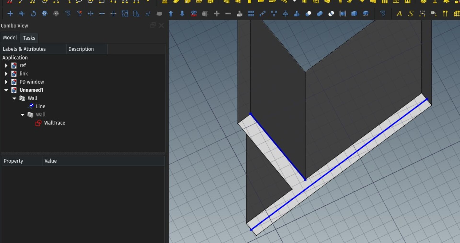
A really important feature of parametric walls in BIM applications is to be able to get the base line on which a wall is aligned. In FreeCAD, although you can build a wall out of almost anything, in most cases you will use a base line, arc or polyline. The IFC format allows you to store this baseline as an alternative representation of the wall. From now on, when exporting walls, this baseline is also exported as an additional representation.
The main issue with this system is that, when reading an IFC file, it's pretty hard to know how to relate the baseline with the wall geometry. You basically get a solid (usually an extrusion of a footprint polyline) and a line, and you don't now how to use the baseline to reconstruct the footprint and solid. There is a way to indicate that the baseline and footprint are related, but it's not more than that.
In the future we could build an algorithm to analyse the baseline and footprint and deduce how the baseline must be extruded to reconstruct the footprint, but with recent developments of the importer (see below), I wonder if that's such a useful path... It seems to me more interesting, after the wall has been created, for the user to be able to select which edge must become the baseline. This would allow you to completely change the way an object is constructed, for example change the alignment from left to right. This needs more experimenting!
Multicore IFC importer
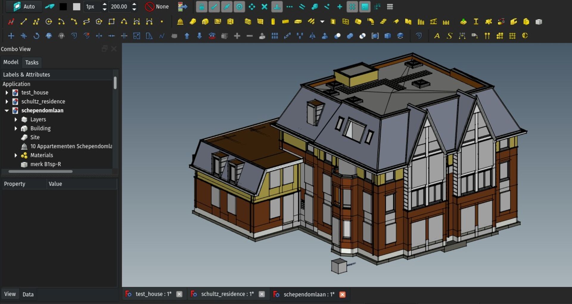
This is certainly the most exciting improvement of this month. IfcOpenShell, the engine behind FreeCAD's IFC import/export functionality, has implemented a multi-core mode, able to use more than one CPU process simultaneously to process IFC files. Together, it also implemented a very efficient iterator that steps over the different elements of an IFC file with much more efficiency than the default query system we were using until now.
I started implementing the iterator in FreeCAD's IFC importer, and, although it still crashes a lot when using more than one CPU process, even with just one, the results are baffling: Importing IFC files in FreeCAD now takes about 1/5 of the time it uses to take with the former importer.
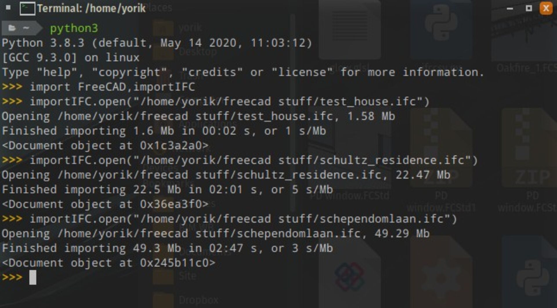
With this, a fairly large, 50Mb IFC file opens in a couple of minutes (in console mode, it's a bit slower when doing it from the GUI). No more need to turn things like furniture off. There are many strategies to set up and explore to work with much larger files, such as working with subfiles (using References or App Links), but in any case it really opens the door to working with much larger BIM datasets in FreeCAD.
One important detail is that this new importer only creates "dumb" Arch Component objects. It doesn't recreate extrusions, etc. That is on purpose, to make the import as fast as possible, and let users turn individual objects editable on-demand.
You can already do that with the BIM Reextrude tool, which allows you to select a base face of an object and recreate its extrusion, but the idea is to extend this tool even further to recreate different types of objects such as line-based walls.
When you import an IFC file from somewhere else, you almost never want to edit all objects. Only a very small subset, if any at all. So it makes a lot of sense to skip generating a lot of intermediary objects that will probably never be used.
We should also find a way to, when reexporting the model to another IFC file, reexport unmodified objects the exact same way they were in the original file. That would also optimise export a lot.
The code is also much much cleaner and easy to extend, fix or optimise.
To test, make sure you have a recent FreeCAD 0.19 version, go under menu Edit->Preferences->Import/Export->IFC import, and set multi-core level to 0 (no multi-core, using the old importer), 1 (using the new importer but with only 1 CPU core) or any number above 1, corresponding on the number of CPU cores to use. It's always advised to let one core free, so if you have a quad core CPU, use 3. Use this only for testing, though, because I found the above 1 it crashes a lot. But we'll work on it. Even with 1 the speed gains are really impressive, FreeCAD really feels like a decent IFC platform now
On my way to test with gigantic files now!
Export of structural analysis IFC
Together with @jesusbill and @Moult on the osarch community, we set up FreeCAD to export IFC files that are ready for structural analysis. This is a separate "mode", supported by the IFC standard, that contains beams, columns or any other structural elements described as bars with connecting nodes. You can also apply forces and restrictions on the bars and nodes.
When enabling the appropriate option under Edit->Preferences->Import/Export->IFC export, FreeCAD can now export this structural analysis data within IFC files (you can choose to either export only the "normal" model, only the structural model, or both in the same file).
So far, all Structural objects will have their structural nodes exported as IFC structural data, and also all linear 2D elements such as lines or polylines will be exported as structural data as well. I'm not sure this is really useful, but it seemed to me a convenient way to quickly rough-sketch stuff in FreeCAD to get it imported in a structural analysis program.
There is no way to set node restrictions or load cases yet, that should at the moment be done in the structural analysis program, but since the FEM workbench of FreeCAD provides those things, we might think of a way to fetch them and export them together...
So far I don't know of any application able to open such structural analysis IFC files, but @jesusbill is working on the Ifc2CA project, now included within IfcOpenShell, which implements this in CodeAster.
Human figure on the grid
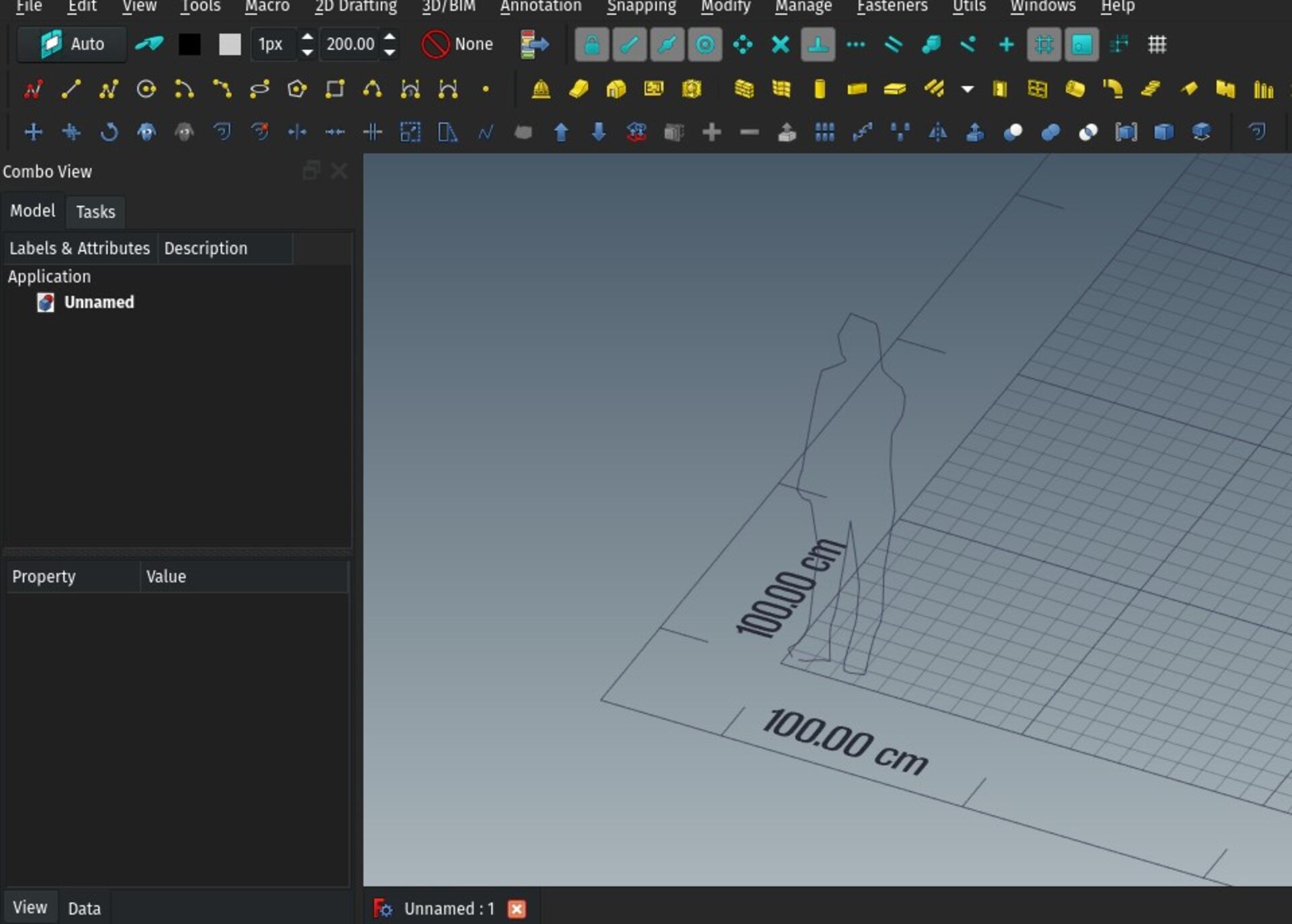
If you have the BIM workbench installed, and the grid extras are turned on under Edit->Preferences->Draft->Grid settings, the grid will show a human figure in the bottom left corner. This is a very small thing, but it seemed useful to me to get a visual sense of the working space. Time will tell if people like it or not!
That's it for this month, thanks for reading so far, and see you next month!
Comment on this post on Twitter Facebook FreeCAD forum Mastodon - Show replies