Categories:
-
3d 96 articles
-
animations 16 articles
-
architecture 47 articles
-
blender 98 articles
-
bédé 19 articles
-
techdrawing 24 articles
-
freecad 189 articles
-
gaming 1 articles
-
idsampa 8 articles
-
inthepress 8 articles
-
linux 57 articles
-
music 1 articles
-
nativeifc 30 articles
-
opensource 266 articles
-
orange 4 articles
-
photo 16 articles
-
projects 35 articles
-
receitas 176 articles
-
saopaulo 18 articles
-
sketches 163 articles
-
talks 25 articles
-
techdrawing 24 articles
-
textes 7 articles
-
trilhas 3 articles
-
urbanoids 1 articles
-
video 47 articles
-
webdesign 7 articles
-
works 151 articles
Archives:
-
2007 22 articles
-
2008 32 articles
-
2009 66 articles
-
2010 74 articles
-
2011 74 articles
-
2012 47 articles
-
2013 31 articles
-
2014 38 articles
-
2015 28 articles
-
2016 36 articles
-
2017 41 articles
-
2018 46 articles
-
2019 59 articles
-
2020 18 articles
-
2021 20 articles
-
2022 7 articles
-
2023 25 articles
-
2024 14 articles
FreeCAD BIM update 25
Hi there,
Time flies way too fast, and it's high time for another report about BIM development in FreeCAD. I know it does not make much sense to call these "weekly" nowadays, but I still hope at some point I'll be able to get back to that rhythm...
Without further ado and whining, let's get to the meat of it. These last weeks I've mostly been busy fixing a lot issues that have appeared after the recent BIM/NativeIFC merge, and I'm please to say things are pretty stable already for the forthcoming FreeCAD 1.0, and the NativeIFC system, although still new and somewhat fragile, is already pretty much usable.
Version 1.0 is around the corner, we have already issued a second release candidate which you are encouraged begged to try, and we still have a list of 11 blocking bugs we're trying to solve before we can release the final version. So hopefully we are very close now.
But I've also managed to advance on my own NativeIFC roadmap and we have a big chunk coming ahead, right after 1.0 is released:
IFC 2D support
The IFC format, as you know, is used primarily to exchange 3D models of buildings. However, there is a lot more in it, and Bonsai (ex-BlenderBIM) has already made a lot of development in that regard. Basically, it is possible to embed 2D drawings, such as plans and sections, complete with annotations and everything, inside an IFC model.
Well, I'm happy to report this is now working in FreeCAD as well. It is possible to open an IFC file issued by either Bonsai or FreeCAD, and view, edit and print the 2D drawings inside.
This is not 100% complete, mind you, so far we are just supporting in FreeCAD the same set of 2D entities as Bonsai: linework, hatches, texts, dimensions and view definitions (aka section planes in FreeCAD). So when opening such a file in FreeCAD, at the moment you still need to generate a 2D view from it. Basically it will still need some testing to get an idea of how we should do that automatically.
So for example, you take a small model like this (modelled in FreeCAD, opened in Blender + Bonsai):
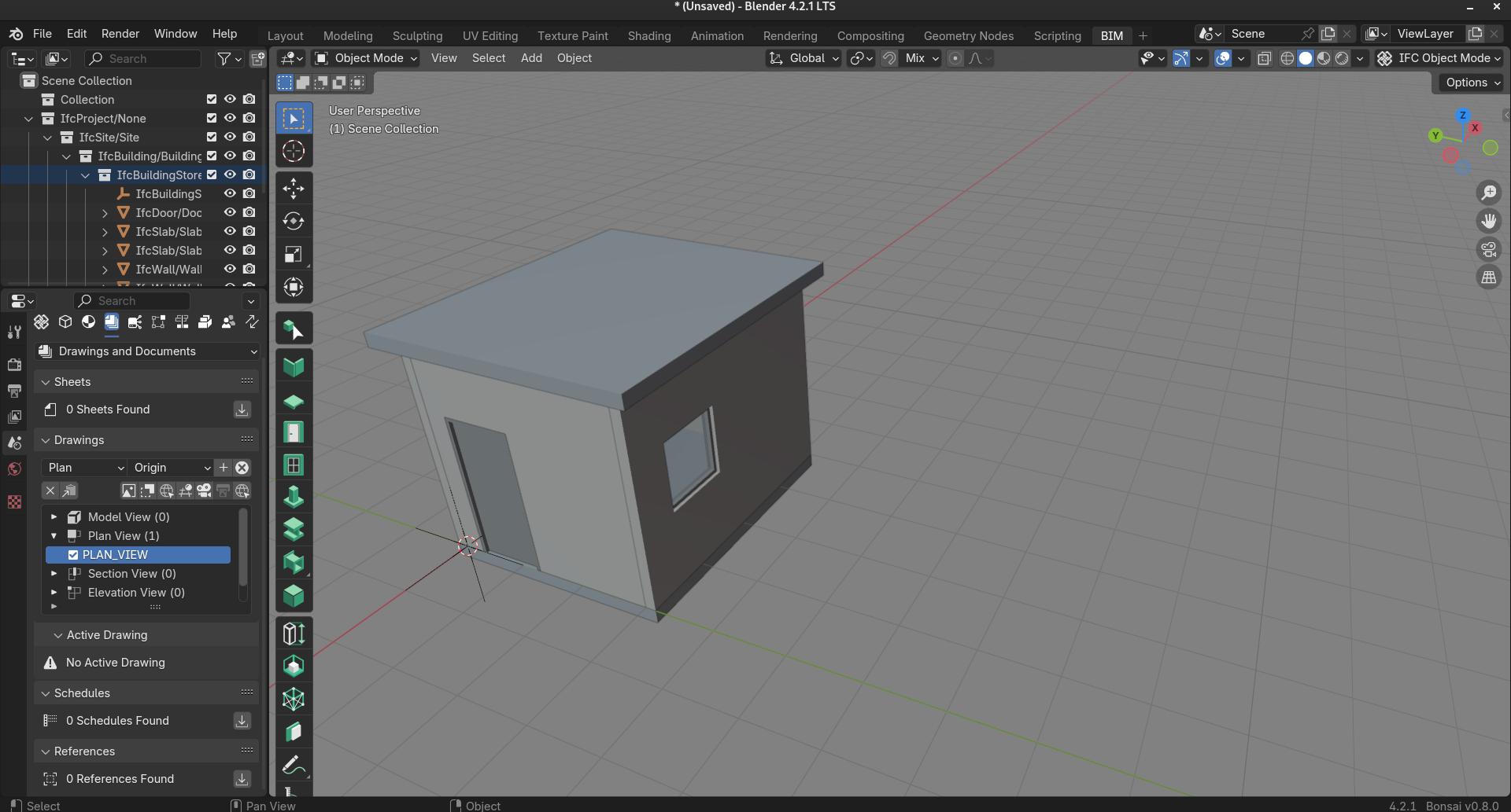
In FreeCAD, you would just add a new group, then dimensions, texts, linework, and a section plane to that group. When dropping that group onto the IFC model, everything will hopefully "just work" and everything be embedded into the IFC file.
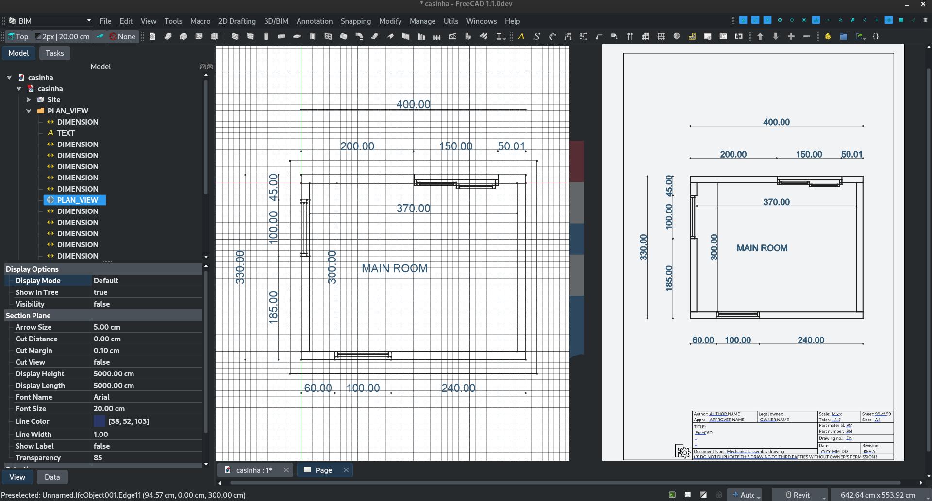
If you open such an IFC file in FreeCAD, being produced by FreeCAD like explained above or by Bonsai, you'll see the group containing a section plane and different annotations. You make a 2D view from the section plane, as usual, and you get something printable:
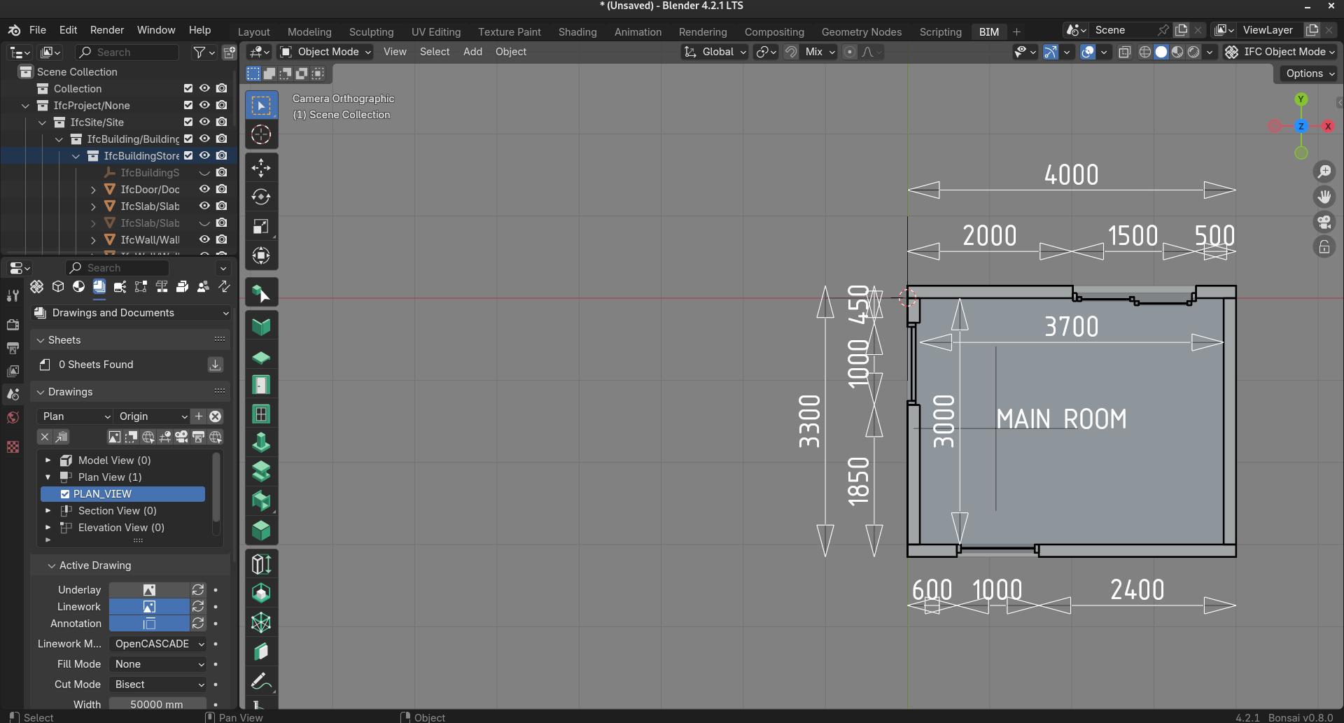
And if you open it in Bonsai you get exactly the same thing:
And from either Bonsai or FreeCAD it can be exported to SVG:
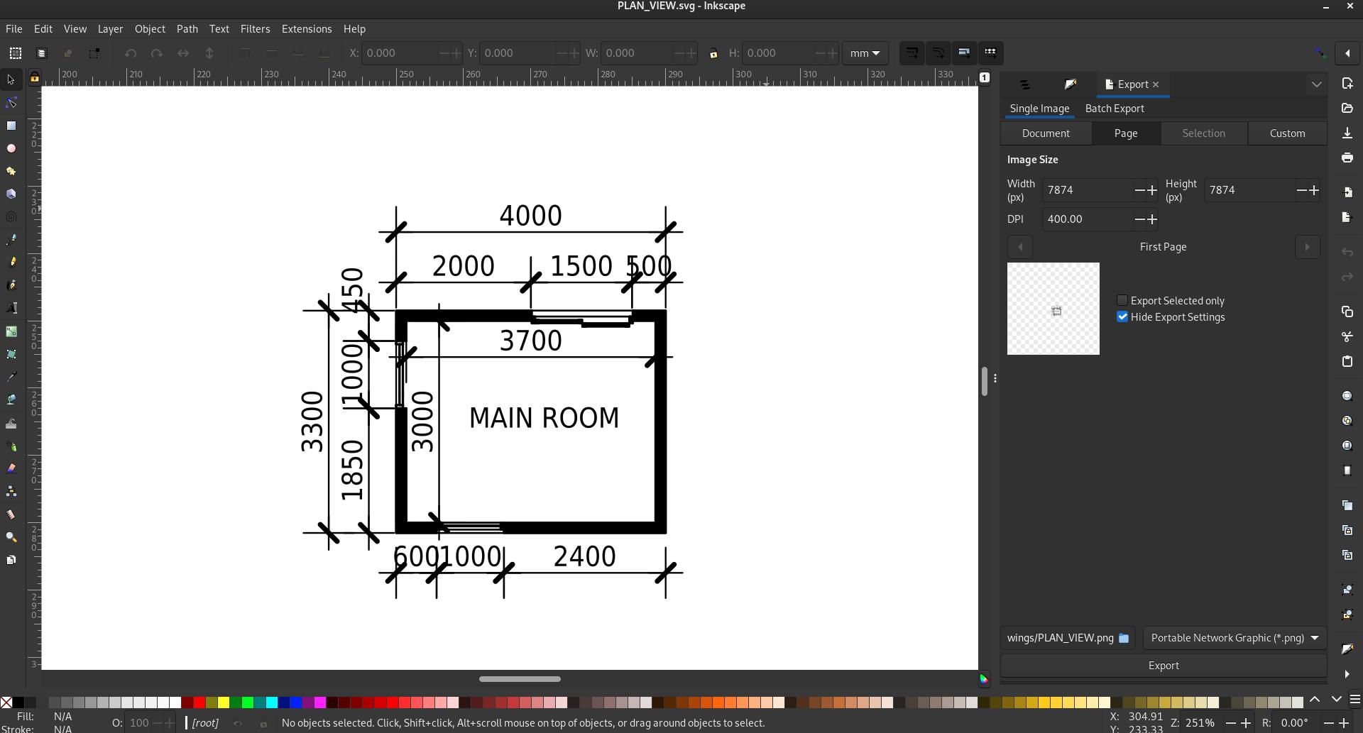
Of course rendering parameters (text size, dimension style, etc) still differ from Bonsai to FreeCAD. At the moment, I see this as not really a problem, with the same IFC file you just choose the app you prefer for output. But of course we will work further on supporting all this styling. Remember, as this is native IFC, nothing is lost, whether you edit the IFC file in FreeCAD or Bonsai.
The changes above are part of Pull Request #16629.
Better document production workflow
This is part of the larger BIM Views upgrade I talked about in an earlier post. The workflow for creating 2D drawings in the BIM workbench has been a bit streamlined and hopefully will feel more intuitive:
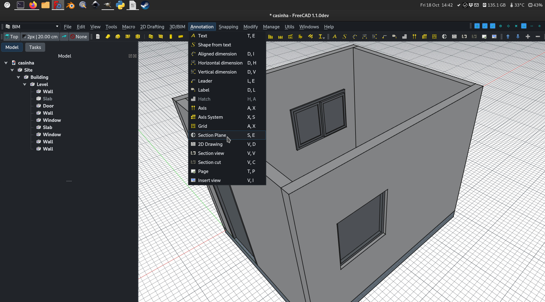
The typical workflow to create a 2D drawing now involves the following steps, and the buttons order reflects that:
-
Creating a section plane, and placing it correctly in the model. That's what we've been doing up to now.
-
Creating a drawing view. The drawing view is simply a BuildingPart that has been modified to be recognized as a 2D drawing (and stripped out of some attributes like level, height, etc). You could still use a standard group here, like we were doing in the past, but using a BuildingPart has a few additional advantages: It defines a working plane, you can move it and it will also move its contents, and it has a nice "title" that shows in the viewport. But fundamentally, the drawing view is just a container for the components of your 2d drawing.
-
Create a section view and if needed, a section cut from your section plane. Both tools produce a Shape2DView, but the first one in "solid" mode, which shows projected lines from what is viewed by the section plane, and the second one in "cut lines" mode, so it shows only the cut lines (the intersection between the section plane and the model). In plans and sections, you will want both, and give the section cut a bit thicker line width, in elevations you will typically only need the section view, as there is nothing to cut. Then, of course, you place both these objects, in the drawing view.
-
Create all needed annotations like dimensions, texts, 2D linework, etc... and add them to the drawing view.
-
Create a TechDraw page using the "page" button. Unlike the TechDraw buttons, this one will pop up a dialog to let you select a svg file to use as a template (and remember the last used template).
-
Once you have your drawing view and your page, select both and press the insert view button. This will create a TechDraw view on the page, showing the contents of your drawing view.
As explained last month, the BIM Views panel also now allows you to quickly switch between model view, drawing views and page views.
This will still need some tweaking and adjustment to make it really smooth, but I feel we are on the good path...
This is part of Pull Request #15836.
That´s it for this edition, thank you once again to everybody who sponsors my FreeCAD BIM work on Patreon, LiberaPay or GitHub!
Cheers
Yorik
Comment on this post on Twitter FreeCAD forum OSArch Mastodon - Show replies