
YORIK’S COFFEE CORNER


@Willem yeah, that's highly overdue... But check out Regis's videos, there is a LOT of amazing content https://www.youtube.com/user/RegisBBNT/videos
@Zbigniew yeah just saw that too! Not sure how to make use of it though...
Usable but surely would need rewriting a lot of code?
Thank you for your reply.
I must admit I got a lot of appreciation for you as an architect who could learn programming the tools for architecture )). As to FC workflow: I made a few 'approaches' to arch.module, having some earlier experience with revit, archicad, autocad architecture etc. and just could not figure out FC arch. workflow so far ))). But I take your promise as a good sign and wait for FC 17 release. Btw. Best New Year, 2018 wishes !
Merry Christmas and a good FreeCAD New Year
Yes, Blender cycles is considered, but that will soon be supported natively by the FreeCAD importer I'm working on. Of course, there will be tuts.
About the workflow with FreeCAD, it is indeed a very different application from its commercial counterparts, specially for an architect (people using for ex. solidworks have less difficulty, and children have no difficulty at all). But all long-time FreeCAD users will tell you that it's worth the effort...
Ive been watching Freecad for a few years now, I am sure itll achieve production maturity.
I have 2 questions/suggestions: Is Blender's Cycles engine to be considered as render for Freecad?
Would you publish a tut/workflow from above case study?
I have to admit /I am an architect also/ Freecad workflow seems not so much intuitive to me so far..
Cheers,
Zbigg
FreeCAD Arch Development News - November/December 2017
Hi all,
First off, sorry for the delay, I was trying to finish the new Render workbench (see below) before posting this report, because otherwise there is not much exciting stuff this month, and it ended up taking more time than I thought, because I kept experimenting a lot until arriving to a good solution. And since not much more will be happening this year, given the coming new year events (a good friend of mine calls this The Great Intoxication) I'll exceptionally make one report for two months, if you don't mind. But I'll give you some more news before the January report.
I'd also like to take this opportunity to thank you all who contributed to my Patreon campaign (or Librepay) this year, it has triggered some big changes for me, which took (and are still taking) more time than I thought, you don't turn into a part-time programmer overnight, but it is a really cool process, and, truth be told, during last year's dire economical crisis in Brazil, this FreeCAD "job" I now have thanks to you guys helped me a lot to keep the boat afloat. Thanks a million for that.
Basically FreeCAD development has now entered "feature freeze" mode, in preparation to the upcoming 0.17 release. I can hear the question rushing from your hearts: When???
There is unfortunately no answer to this yet, as some of you know, a motto we have at FreeCAD, that we really like a lot  is: "It's done when it's done". This can be interpreted in many ways, you might think "lazy developers don't want to work hard enough!" but it is not that. It is very important to all of us to be able to release when we think it has reached the correct level of quality. As the project grows too, there are more and more developers involved, and more and more features weren't touched at all by one of the core developers, and it takes time to have everybody focus on fixing bugs. In a sense, FreeCAD has its own rythm, and we try to make sure everything that needs to be done is done before releasing.
Also, but this is more my personal opinion, working on an open-source project is awesomely cool. You don't have a boss telling you how you must do your job, no schedule, no deadline, no need to do this or that today, you decide what you want to do, how you want to do it and when. Total freedom. And I believe one of the main reason why open-source projects thrive well is this. People like to work on them, they have cool communities full of entusiast people who stick there for a very long time. And I think it is important to keep an open-source project a very cool and awesome place for developers to be. And I'm not sure very strict projects with lots of schedules and roadmaps are as cool to work with as FreeCAD  I'd like to hear it if you have a different opinion, though.
Also in the case of FreeCAD we have a pretty permeable workflow. Development versions are easy to obtain and install, even side-by-side with the current "official" release, and are usually very stable. Most long-time FreeCAD users only use development versions. So the urgency to release official versions is low.
So, we are now in feature freeze mode, which means we don't add new features to the code anymore (at least we try to), we concentrate on testing and fixing bugs. There are still a couple of nasty ones to be fixed, but in general the process is going well.
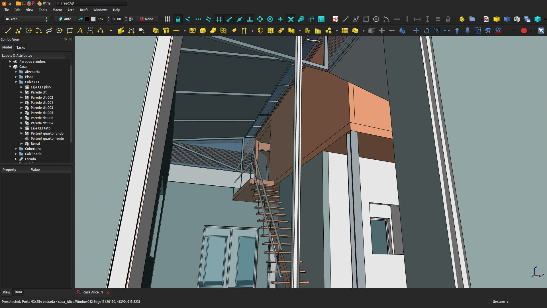
Regarding the Arch workbench specifically, I am currently developing an architecture project with it, and using it as a test bed to test all possible scenarios and find bugs (and fix them of course). There is unfortunately nothing very exciting to share here, it's mostly small things, but this is an important phase.
All in all, I think the Arch workbench is in pretty good shape for the coming release, we of course still don't have all the features we want for it to be a full BIM application, but the existing tools grew a lot in stability, versatility and usability. For some of them like the structure or panel tools, I believe we're not far from commercial counterparts.
Also, there are now several tools and addons around Arch, such as Reinforcement or Flamingo, that, together with Arch, are building a much bigger and more complete BIM ecosystem in FreeCAD.
There are many things you can do to help to speed up the release process, if you are interested. For example translating FreeCAD, helping with the documentation or more generally, do some work with FreeCAD and help to find bugs. As always, the forum is the best place to go if you want to help.
The Render workbench

The Render workbench is a new addon workbench I've developed last month. It is meant to replace the built-in Raytracing workbench of FreeCAD. The main reason is that the Raytracing workbench wasn't really made to be extended with other rendering engines, but these engines get obsolete quickly and new ones pop up all the time, so I thought it was worth starting a new one from scratch.
The Render workbench is coded in Python, because since the rendering itself is performed by another application anyway, there is no critical speed issue here, so the speed of C++ code is not really necessary, and it makes the workbench much easier to extend by other people. I also took extra care of making it simple to understand and extend, you basically only need to add one new file for each new renderer, and write 3 functions inside: One that writes the position of the camera in the file format of the renderer, one that writes the geometry of a given object, and one that is called when the "Render" button is pressed.
So far the two original engines of the Raytracing workbench are supported (Pov-Ray and Luxender), plus a new one, Appleseed. Other such as Blender's Eevee and OpenCasCade's CadRays are on my todo list.
The Render workbench works exactly like Raytracing: You start by creating a Render project, then add your objects to it. You can tweak some things like color, transparency, etc (the Render workbench also supports FreeCAD materials, which turns it the third workbench with material support, after FEM and Arch), and finally press the Render button to create the rendered image. And the Render workbench uses the same templates as Raytracing, in the good tradition installed with TechDraw and Drawing.
This is still pretty new, but in the coming days I'll try to produce some good-looking images to post on the forum.
That's it for today, thanks once again to everybody who helps me on Patreon or Librepay, it's really thrilling to see what this can produce, this year has been very rich in new features, I can't wait to see what we'll do next year!
Cheers
Yorik


koydl.de/show_FreeCAD_maintainers/freecad.mp4
0.16 works as expected.
Any idea, what's going wrong here? Thanks.
Doesn't QGIS import DXF directly? In any case FreeCAD doesn't export to KMZ/KML or shapefile... At the moment there is no tool to geolocate things


There is a "merge point clouds" option in the Points menu
Thank you very much for your valuable aportation. When I convert the contours into points I get several points cloud, each one associated to the respective contour. So, I would like to know how to join them into a single entity.
Thank you in advance
Best Regards
Jacob


Good to hear you now have more time for it.
Thanks for the blog and keep the good work going!
FreeCAD Arch development news - October 2017
Hi there,
Time for a new report on the development of Architecture and BIM tools for FreeCAD. Remember, you can help me to spend more time working on this, by sponsoring me on Patreon, Librepay or directly (ask me for a PayPal email or bitcoin address).
Campain and future development
Since I just recently opened the Librepay account, and the Patreon campaign is progressing much (I'm receiving above US$ 600/month already, thanks so much everybody!) I think it's time to be a little more serious and transparent about it, and give you guys some more "accountable" feedback on how the money is used. I'll start using this report to give a sum of how much I receive each month, all crowdfunding accounts together, and also make a bit of a better plan.
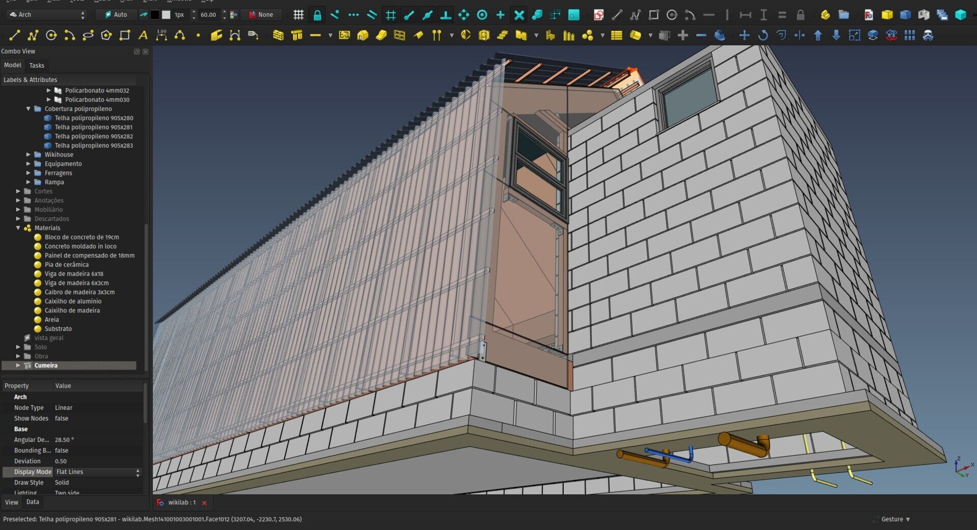
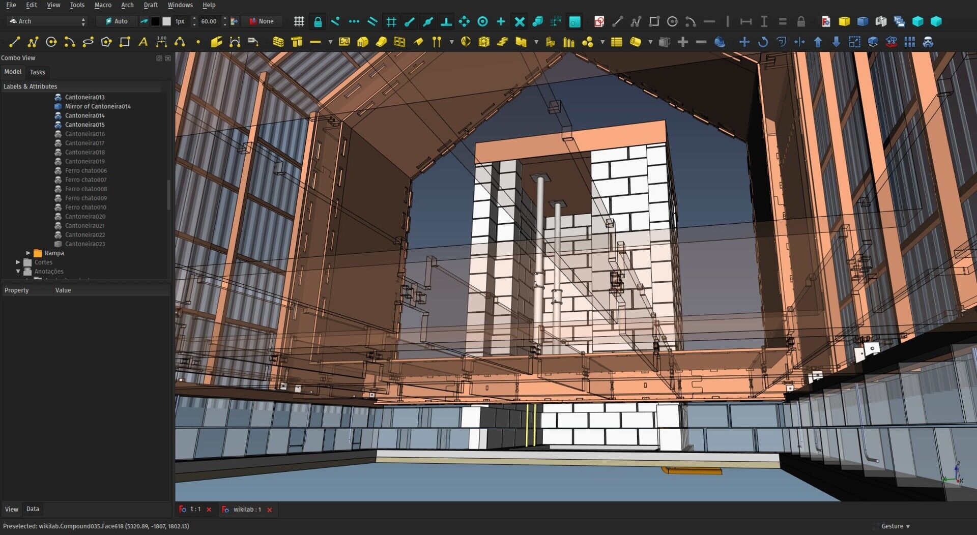
As you know if you read my last article, I just returned from the US, and we are also now finishing the WikiLab project (Grand opening is on next friday, november 10th). So I have been a bit away from FreeCAD coding for some time. But I've been saving the money from this campaign, and I'm now getting back to it, and it's quite refreshing! I have many ideas to work on, that I'm in the process of classifying. Basically I am currently working on two main ones (see below), and I'll also start attacking my overdue issue queue on the FreeCAD tracker, and I also have this "small" list of smaller items/issues that have either to be checked further or solved or implemented:
- Publish FreeCAC manual as a printed book (it's reviewed already, almost ready)
- Add visual feedback to rectangle, circle, polygon Draft tools when entering dimensions via keyboard
- Fix IV mode in Sketchfab exporter
- Allow to draw a beam/column directly, like walls
- Add option to make Length autofocused when drawing line/walls, so one can indicate a direction with the mouse and type a length, same as AutoCAD does
- Move back the Arch Floor concept to Arch Cell (like it was before), so the floor object (the name is wrong anyway) can be used to stack objects together in any form youmight think, not only by level/floor
- Xrefs/lightweight embed objects from same file or other files - experiment further
- Add a command to move selected objects to construction group
- Work further on PropertySet type (a property that can contain other properties, tremendously useful for IFC property sets)
- Allow to auto make a Window from solids (auto recreate base wires and extrusions)
- Selection view - When typing in the search box, add an option to change selection on Enter only, otherwise, starting to type the first letters makes huge (and slow) changes in the selection
- SArch materials library - A software-agnostic table of materials used in construction, with properties, color, generic textures, etc
- Refine material editor - allow easy and proper editing of material properties with appropriate widgets (QItemDelegate)
- Parking slot object and maybe develop a framework for all that category of custom, mostly-2D-but-not-necessarily-only-2D objects used in BIM work: parking slots, rainwater grids, etc...
- Section/elevation symbol - Allow to easily add these symbols on a TechDraw sheet manually
- Align TechDraw views - add a way to align different TD views made with Arch Section Planes
- Experiment with Coin-based 2D views
- Make all window parameters accessible in the property editor (O1, O2, W1, etc..)
- Experiment using App::Part in Arch Cells
- Better multi-dimensions like in Revit - refine the coin representation to reflect multiple dimensions
- Level marks
- Door/Window marks
- Room finish marks
- Auto section/elev marks from section plane
- RCP plan
- Allow to convert multilayer wall to multiple walls and vice-versa
- Make all Roles available to all Arch objects
- Allow to change Draft Label's target object
- Add Rebar length property
- Solve "length not working" in walls
- Addon manager - allow to update all installed addons at once
- Export meshes to IFC and handle hi-res objects
- Task panel for Draft Clones (allow to add/remove objects)
- Add "fill shape" to arch sections
- Taper for structural objects
- Remove background from offlinedoc css
I should really transfer all this to the bug tracker...
Current work
I'm currently working on two things, that are not finished yet and therefore not ready to be used:
One is a new FreeCAD importer for Blender, that allows Blender to import FreeCAD files. A prototype exists already, but the Python3 version of FreeCAD that is needed by this importer still gives me problems (crashes on opening, etc). But once that is solved, we should have a proper importer again. And it will have a couple of more advanced features too, such as Cycles support and the ability to re-import a FreeCAD file later, and keep all your existing materials (only update the geometry of existing objects).
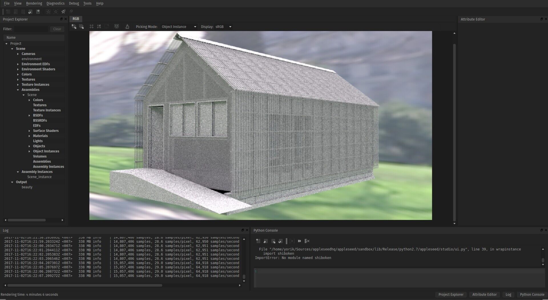
The other feature I'm working on (I have no code that is good enoough to test to share yet) is adding Appleseed as a new renderer to the Raytracing workbench. In a first step I am simply looking at producing an .appleseed file from FreeCAD, that can be fed to the renderer externally (same as we do with PovRay and LuxRender), but Appleseed has a powerful and elegant python (and C++) API too, that can in the futre allow a much more seamless integration, and litterally control and display the rendering progress within FreeCAD. But first things first. I'm also extending a bit the Raytracing workbench code, which is currently C++ only, to allow to add new renderers in python code, which will make it much easier for other people to help and add more renderers.
That's it for this month I'm afraid, thanks once again to everybody who helps me with money, and for your patience with me this last months during the WikiLab construction, I'll make sure it was not lost and reverts into concrete, usable material to push the development of BIM projects with FreeCAD closer to what we all wish it to become!
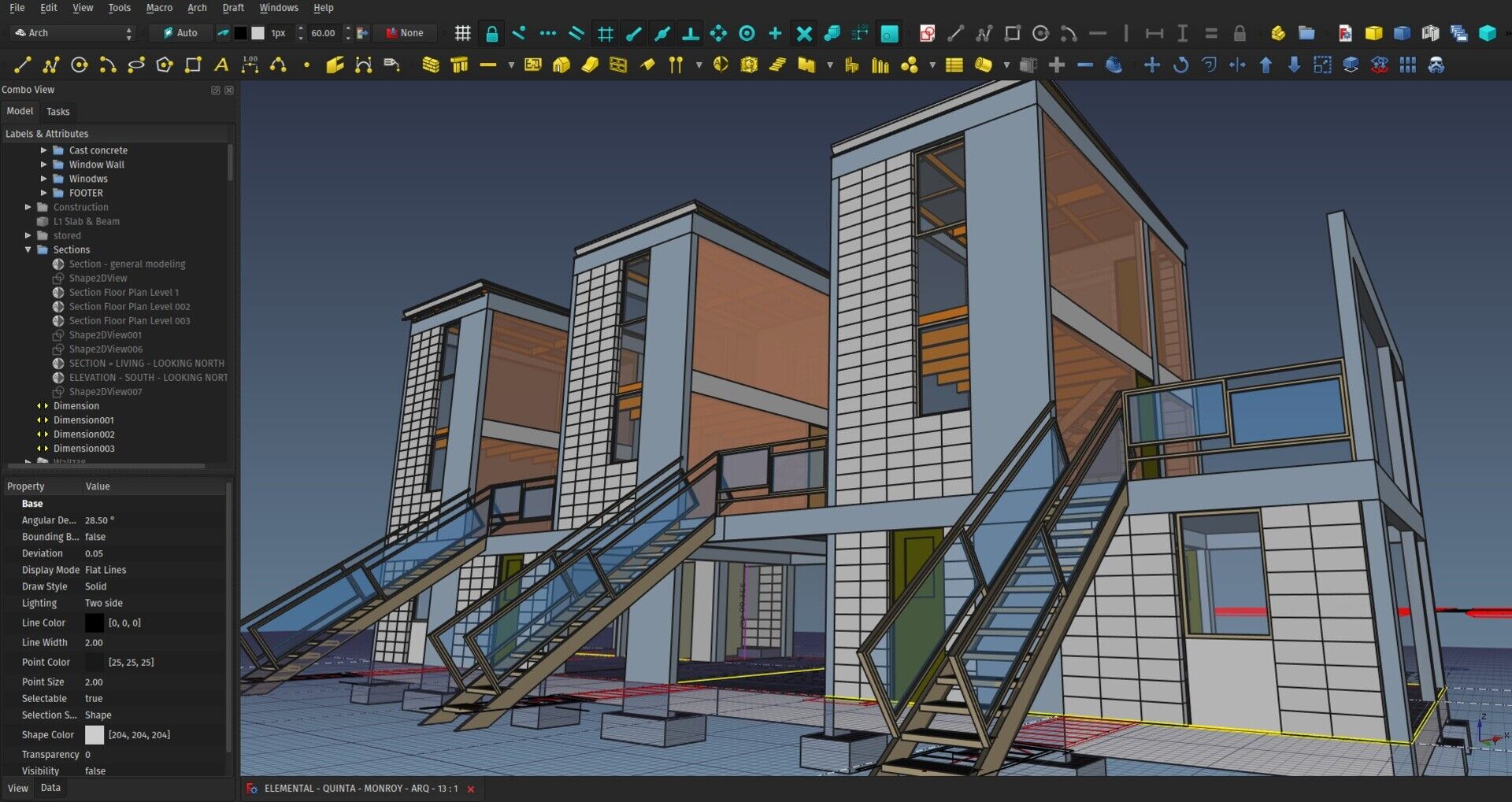
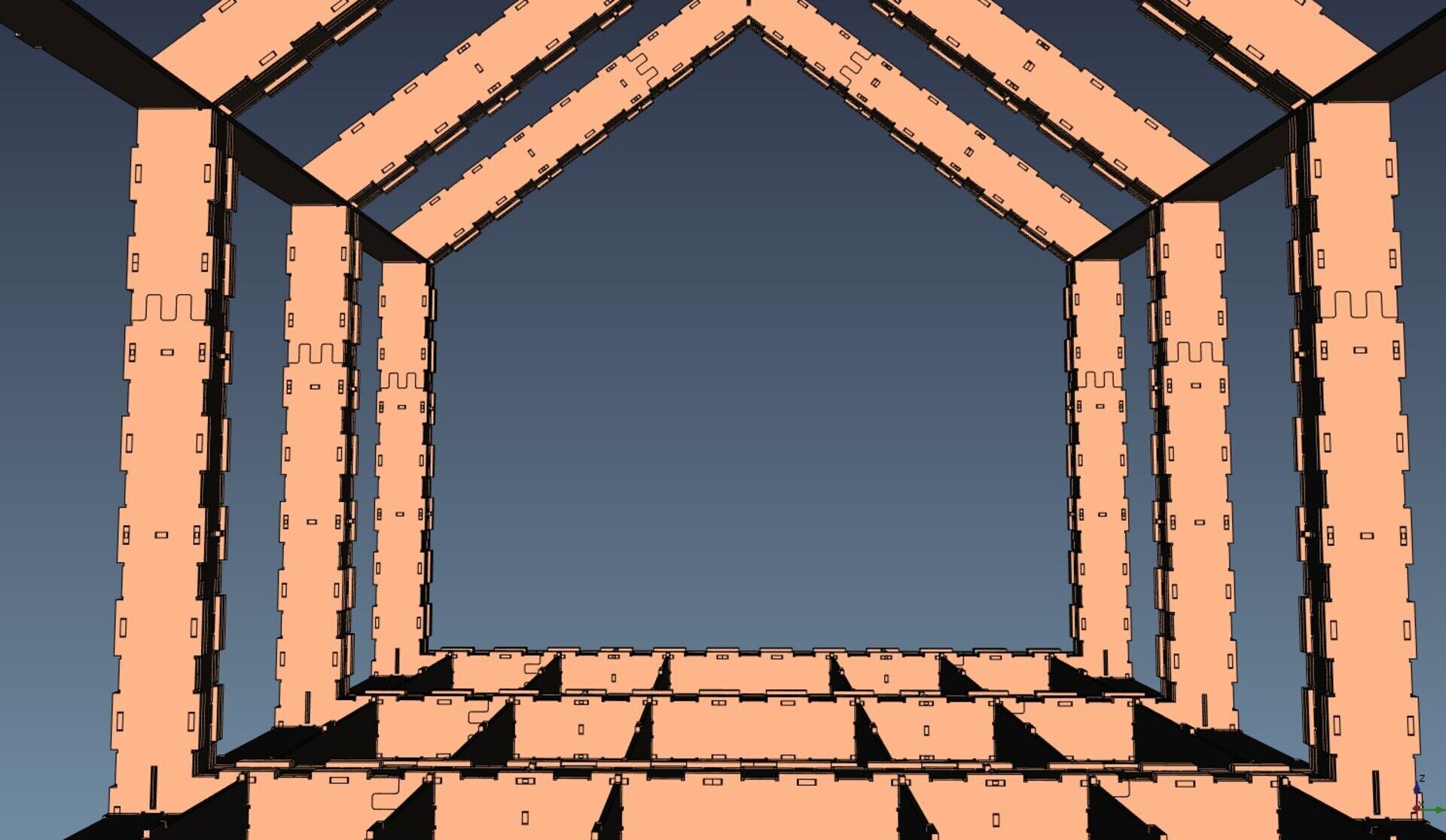
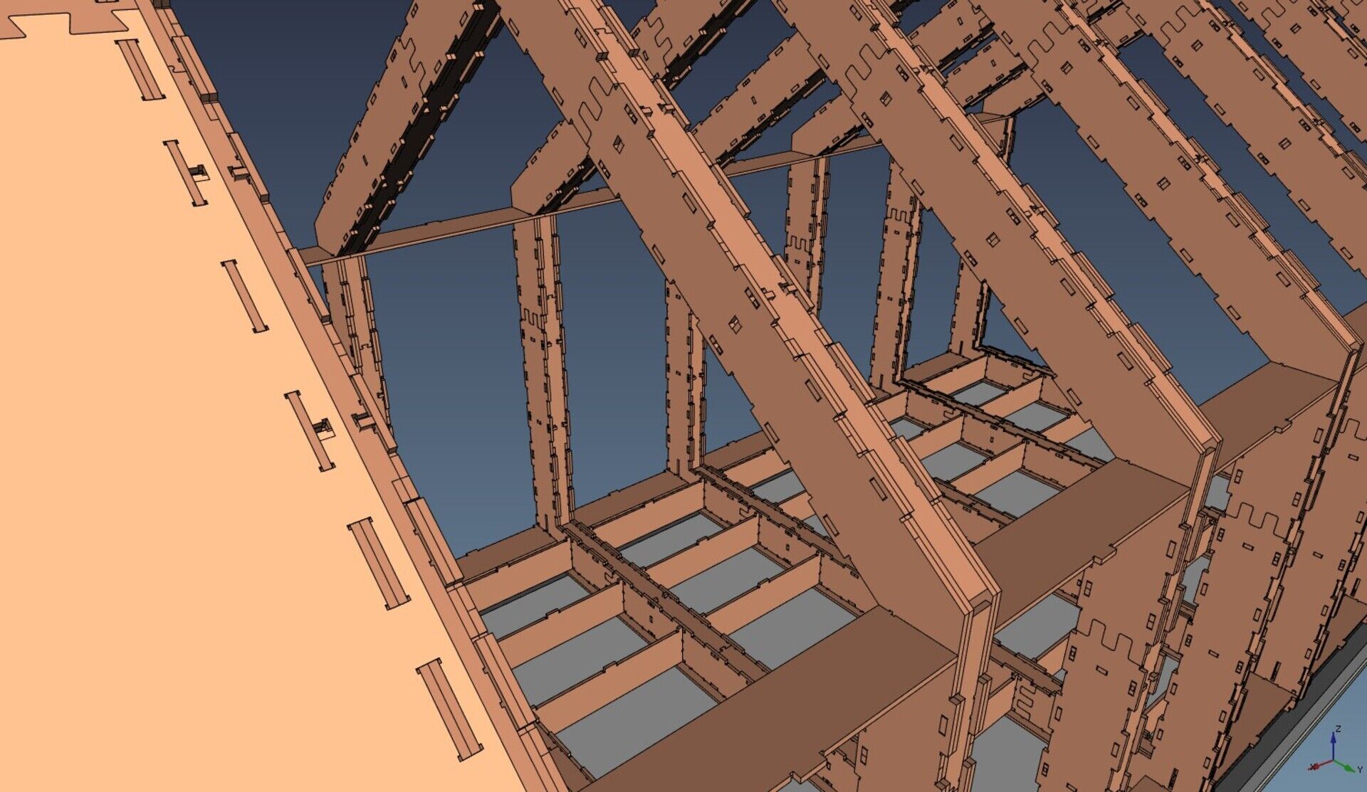
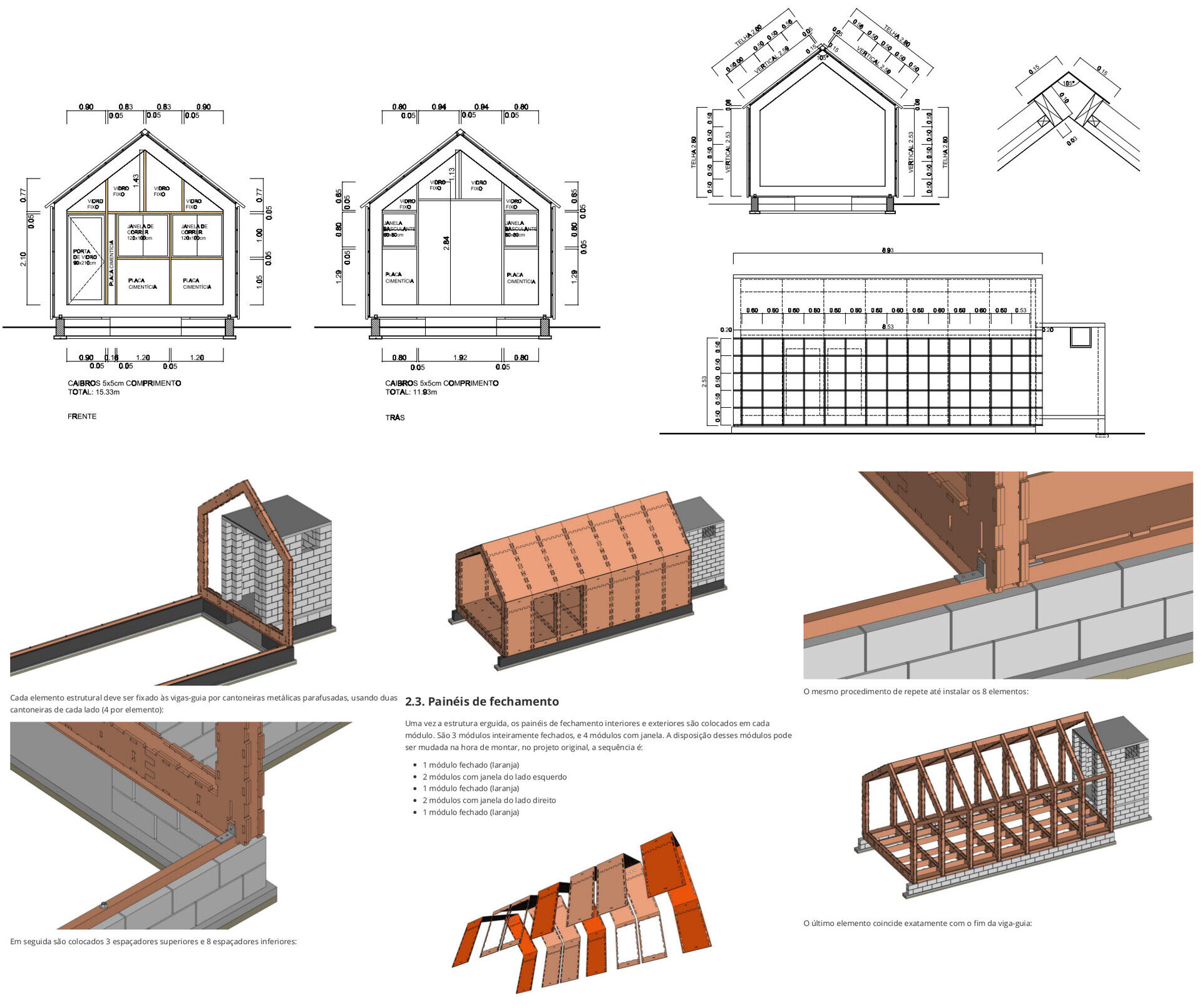
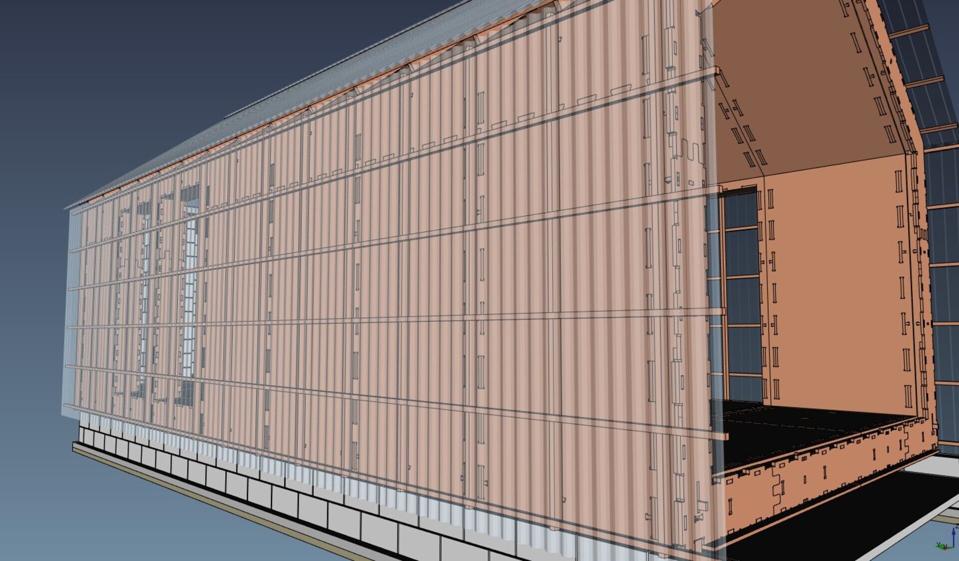
By the way, if you haven't yet, check the amazing work that Regis is doing with recreating one of Aravena/Elemental open-sourced projects in FreeCAD...
so what is the problem here ?
thanks in advance
The Google Weekend
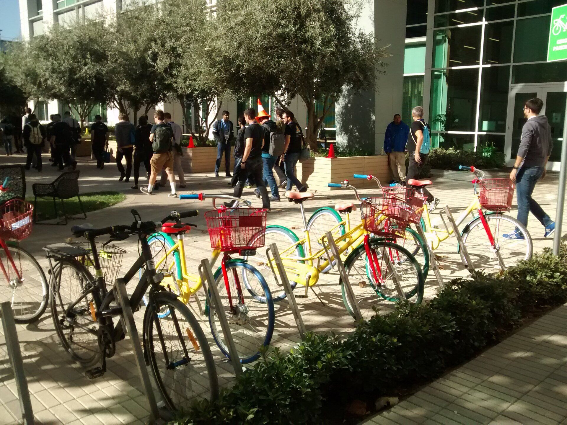
Last week was the Google Summer of Code Mentors Summit, a yearly event organized by Google, where they invite mentors of the Google Summer of Code program, a program that pays students to work on open-source projects. This year, like last year, FreeCAD participated to GSOC. This year we had 4 really good students, and the one I have been mentoring, Amritpal Singh, has done a really remarkable job with his Reinforcement Bar add-on for FreeCAD.
The two years, FreeCAD participated to GSOC together with other open-source CAD, CAM or 3D-related projects, under the "umbrella" of BRL-CAD (they basically did all the organizing). Each year, Google invites a certain number of mentors from each organization to the Mentors Summit, at Google headquarters, in California. So this year, I applied and was lucky enough to get selected. We were five in the BRL-CAD group: Sean, Vasco, Gauravjeet and Inderpreet from BRL-CAD, and myself from FreeCAD.
My main motivation to go was, beside a huge curiosity to see Google inside, I was really eager to know and chat with the BRL-CAD people, our umbrella organization. This project is quite fascinating, it is the first ever registered project on Sourceforge, it is very hard to see it progressing (their website doesn't show much), but it is a huge and powerful application, that stays a bit arcane, and hard to explore by newcomers. But I had a good contact with Sean over the years, and was really curious to know more.
So, the said day, after a pleasant flight (not so pleasant because at he last moment they changed my São Paulo -> Mexico -> San Francisco flight to São Paulo -> New York -> San Franciso, which added 2 or 3 hours of flight time), I landed at San Francisco and shared a ride to the Google headquarters with other people going there (everybody chatting and arranging these things beforehand through a quite interesting open-source chat system called Zulip that got used quite extensively throughout the event. Another chat app, RocketChat was there too, there has been quite interesting debates between the two, I still didn't make my mind fully).
So we arrived at Google HQ, landed to our hotel (conveniently located INSIDE the Google campus (which is not really one campus, they basically own half the cities of Sunnyvale and Mountain View). This is located at the southern tip of the San Francisco Bay (San Francisco being at the North).
And it began immediately, right there. You get your badge, and immediately you can start eating and drinking and chatting, because they reserved some rooms of the hotel and stuffed them with food. After a little while, a transfer bus takes you to one of the Google building, where there is a dinner (two large restaurants plus many cafés, food trucks, etc where everything is for free were available for us basically the whole time), then an opening session, then a couple of lightning talks (3 minutes talks to present GSOC projects), then more beer 
I couldn't get a chance to showcase our GSOC projects of this year though, there were around 300 people wanting to present theirs, and only 50 or 60 slots.
There was also a cool table where everybody dropped chocolate brought from all over the world.
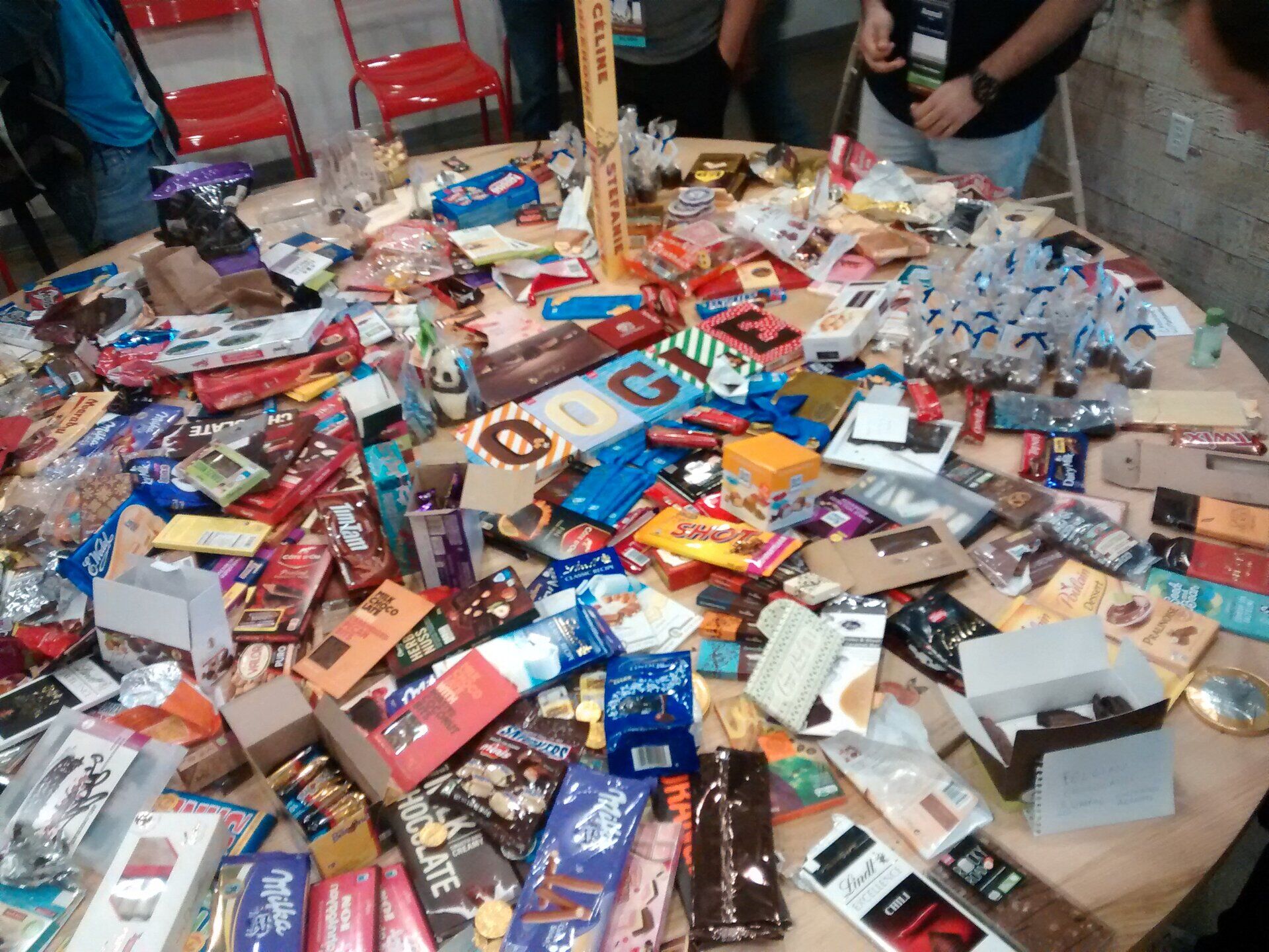
The next day started early, around 7h, with a breakfast at Google, and a whole day packed with "unconferences" (basically small spontaneous lectures or workshops organized by the mentors themselves), more food, more coffee, more chat, more lighning talks, and at the end, of course, more beer, and even roast marshmallow on the open fire, maybe the most epic moment for us non-Americans.
The last day was like that again, and ended up with a closing session in the afternoon.
Like I guess most people there, I didn't attend many unconferences. I basically stayed most of the time in the common areas chatting with people. My impression is that I never chatted so much in two days. At the closing session, the event organizers said they were happy, because they almost never saw anybody alone with his computer, which is something you see a lot in other open-source events. Everybody just kept talking with everbody, all the time.
This is really a magic that Google operated. There were no "boot camp" crap, or "socializing games" or any of those activities to make people socialize. They just provided space, food, drink, and a friendly atmosphere. That's it. Even me who is not a very social person, kept playing that game of going sitting for lunch each time to a different table with unknown people and talk about our projects. I've never seen an open-source event like that.
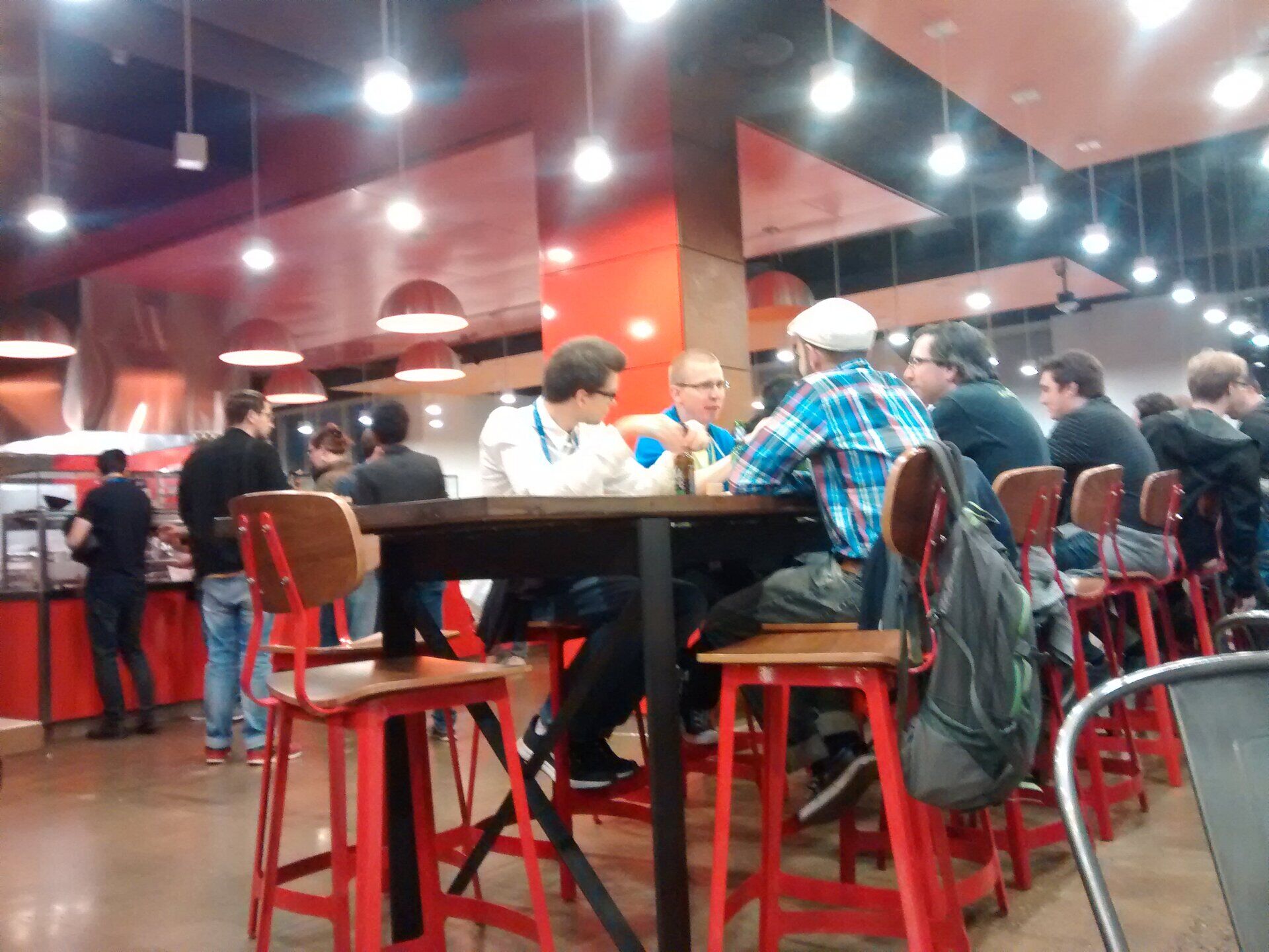
I also tried to get a glimpse at how life is at Google, but couldn't do much. The security schema was tight, no pictures allowed inside buildings, we were only allowed in a very small zone of the Goolge campus, you gave one step out of it and a security guard came to herd you, etc. But all in all I believe they do their publicity extremely well. In my mind everybody at Google would just lie on colored sofas, picking free drinks in an open fridge, would cycle around marvelous campuses on Google bikes, etc. The reality seems actually much more normal, you just sit on your computer and do computer work, and have meetings with your colleagues. But the atmosphere seems really relaxed, there really is free drink and coffee  Other than that, my spying mission at Google failed miserably.
Ah, there were ice cream sandwiches too.

I talked a lot with Ton Roosendaal, the father of Blender. I met him other times already, he always keeps an eye on FreeCAD too. Ton made me a bit anxious, because he told several horror stories about big companies threatening to sue open-source project developers about patents, and in some cases managing to scare developers away of coding completely. We really need to start thinking about that at FreeCAD, and think of strategies to protect ourselves as much as possible.
But we also talked about things we could do together with Blender. The big game engines out there are moving towards offering more tools for CAD software, and we should do something similar, like an easy/1-click, template-based export from FreeCAD to the new stunnigly realistic view mode they are preparing in Blender, called Eevee. Just do a small search on youtube for "blender eevee" and your jaw will drop 
Another person I hanged a lot with if François Beaune (Franz) from Appleseed, a stand-alone rendering engine, similar to Luxrender. I knew Appleseed for some time, and I had a vague idea of trying to integrate it in FreeCAD some day, but this has now become a much better and more realistic plan, after François showed me around the renderer, its API and file format. It is definitely doable, and could become easily the best integrated renderer in FreeCAD. It is in fact possible to make it totally seamless, as if FreeCAD itself would do the rendering. But first things first, we'll start with exporting an appleseed file from the FreeCAD Raytracing workbench first, like the other engines we support already. I'll also take the opportunity to make the Raytracing workbench a bit more pythonic, so new render engines with a python interface will be much easier to add.
And the third really interesting talk I had was with Sean from BRL-CAD. BRL-CAD is a very old project, started by the US Army, which later on released it as open-source. I really thought BRL-CAD had become a pretty inactive project, but this is very far from the truth. The thing is, BRL-CAD's main user is still the US Army, so almost everything that is modelled with it is classified, so it is very hard to publish anything that was done with it, which explains the very sparse image galleries, social media, etc.
However, it is an extremely interesting project. It consists of about 700 commands, a bit like a Unix/Linux operating system where all the base commands you use in a terminal, such as ls, mount, chown, etc.. are actually each one a file, or individual program. Then higher-level tools, such as the desktop environment, uses these commands under the hood to list directories contents, move files, change file permissions, etc.
BRL-CAD works exactly like that, it's a bit like a Unix of CAD... It has a graphical interface, but its real power resides in the vast array of command-line tools. And a modelling tree in BRL-CAD is in fact a shell script!
Another interesting feature in BRL-CAD is that it is capable of managing absurdly huge models. Since it doesn't really have a graphical modeling interface, which must display the model (and therefore compute it and triangulate it, because most computer 3D visualization systems around, such as OpenGL, rely on triangles), they can produce raytracing directly from the model definition and not from a triangulated version of it. This removes a big part of the process that FreeCAD has to do.
So there is much interesting stuff there that maybe we could do something with in FreeCAD. I am not sure what exactly yet, but only the "command line" system itself could easily be integrated into FreeCAD, it's not very different than what we do at FreeCAD level itself between App and Gui.
And BRL-CAD and Appleseed are also working on integration.
After the mentors summit ended, I got really curious about something I read in The Circle, the main character, who works at "some computer firm close to the south tip of the San Francisco bay", likes to take her kayak, go behind the office and paddle in the bay. I saw that the Google campus lies at a few minutes by foot to the bay, and there are many trail paths around, so I went there for a walk, and wasn't deceived. The area is magical, lots of channels and water ways, with here and there a stand-alone, man-made artifact, like a radar, a ship lock, etc...
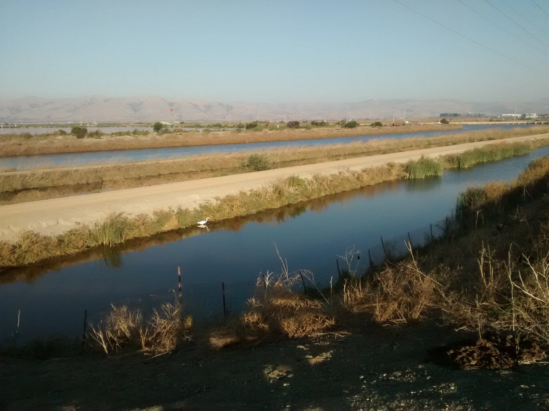
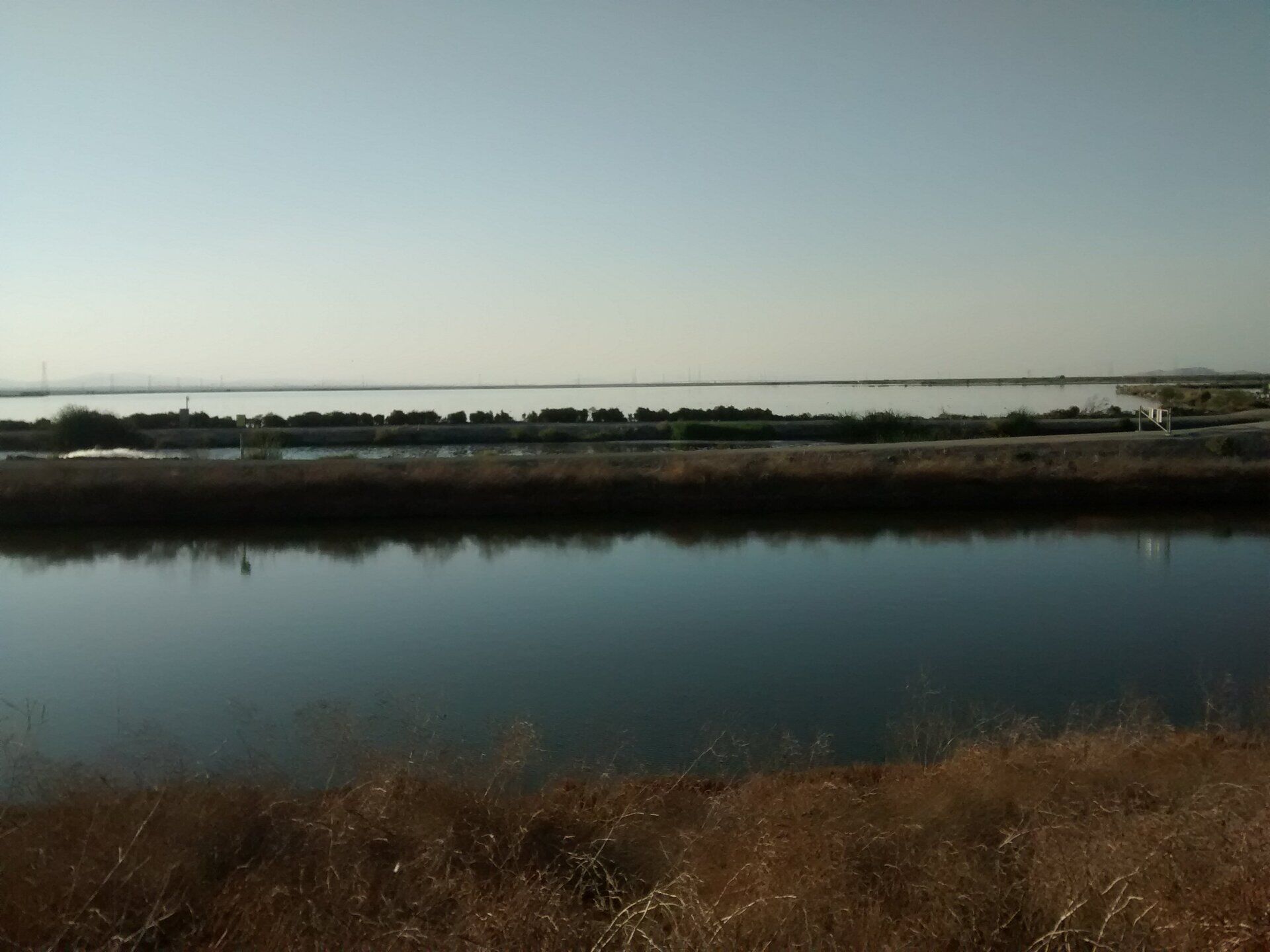
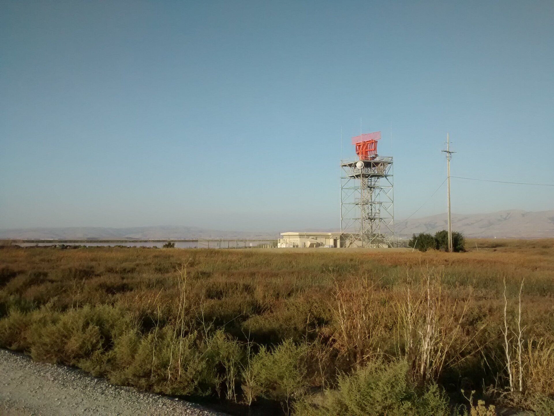
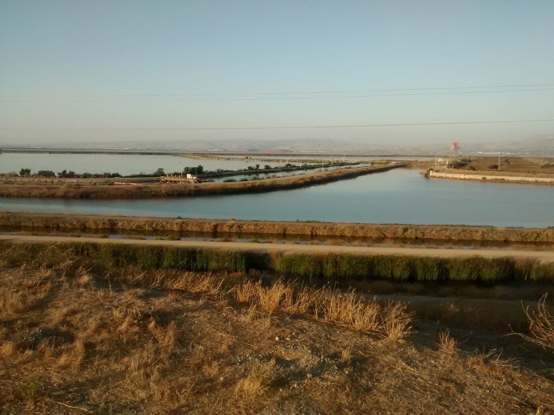
After that I spend a couple of days in the lovely San Francisco, which I decided should integrate my list of magical cities, together with Barcelona, Venice, Cape Town and Rio de Janeiro. I did a bit of drawing too, and checked a couple of architecture icons like the Federal Buiding by Morphosis (impressive "concretization"of everything Morphosis has been saying, but big doubts about the so-called "green building" stuff and the very poor attempts at making the building users "socialize"...), Libeskind's Jewish Museum (really disappointing, very little more than just a "funny space" , or the MOMA by Snøhetta (couldn't enter unfortunately, wrong planning).
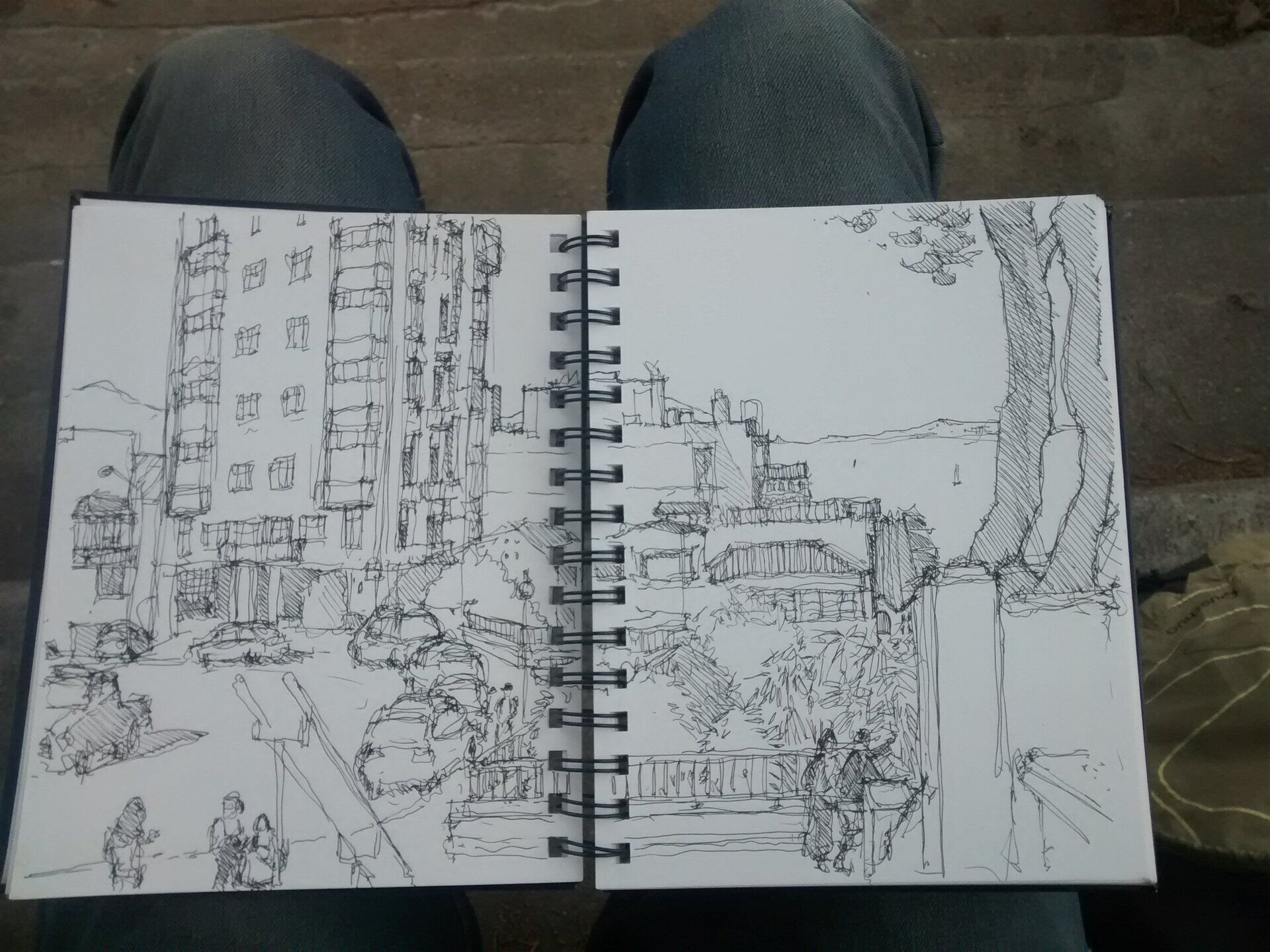
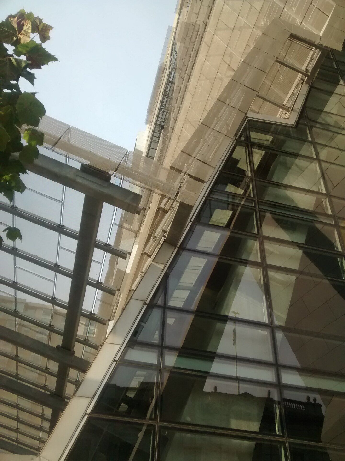
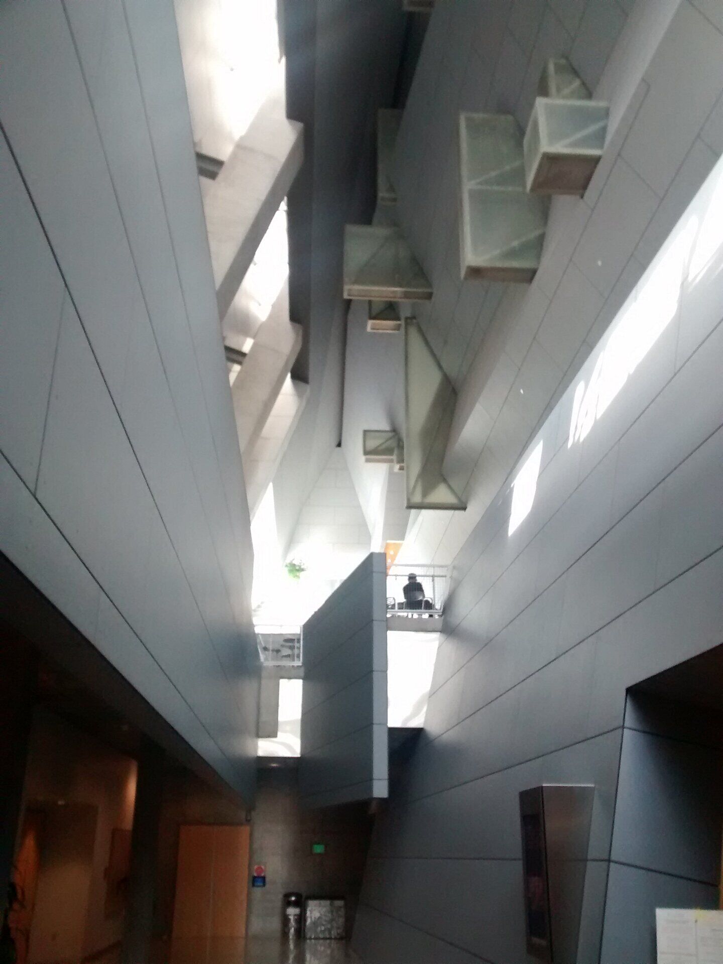
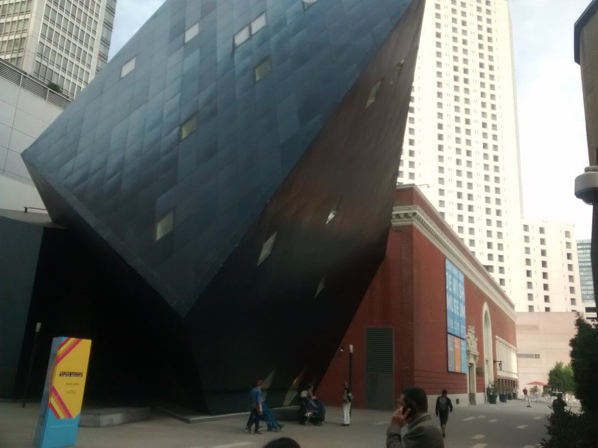
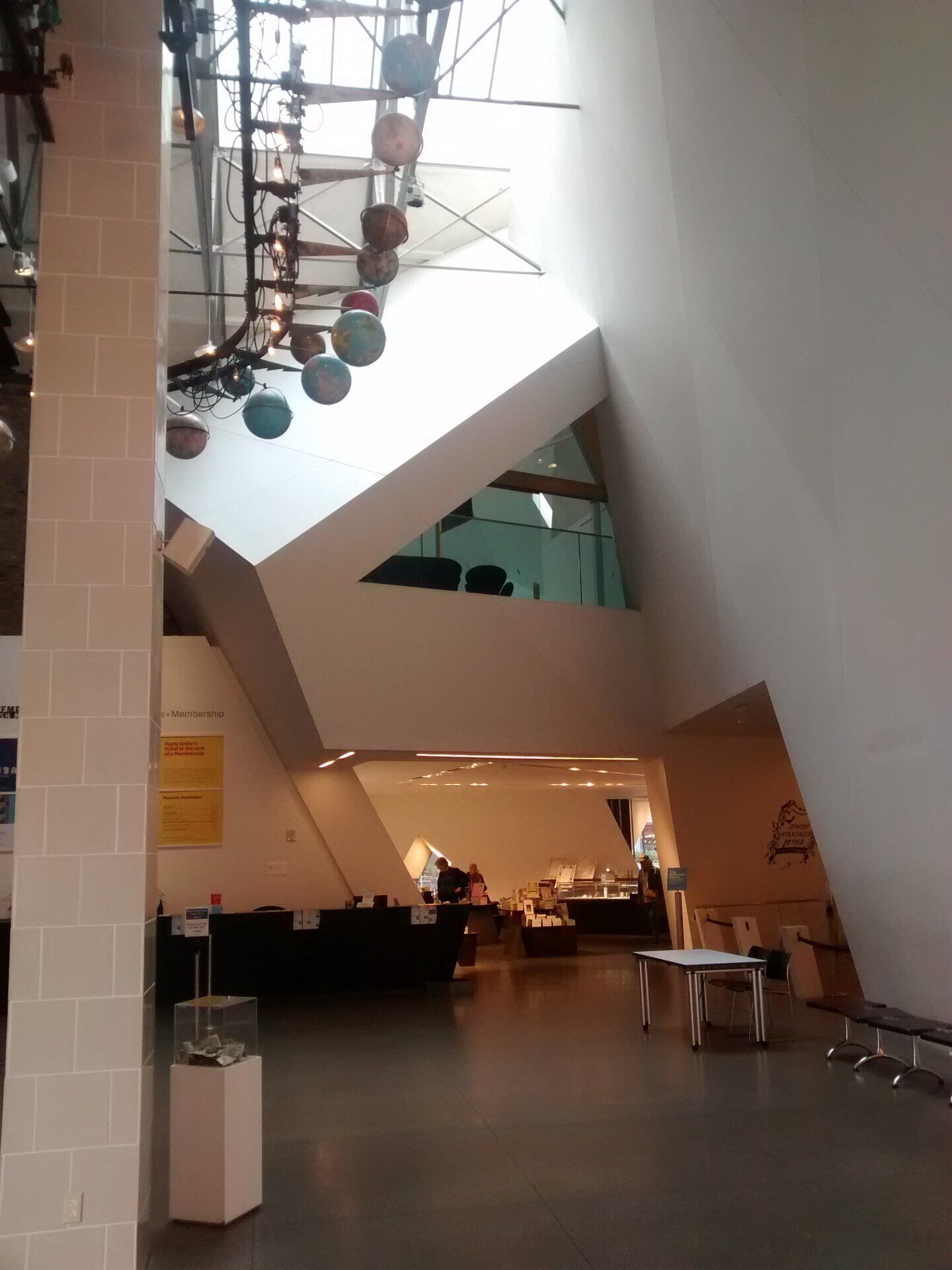
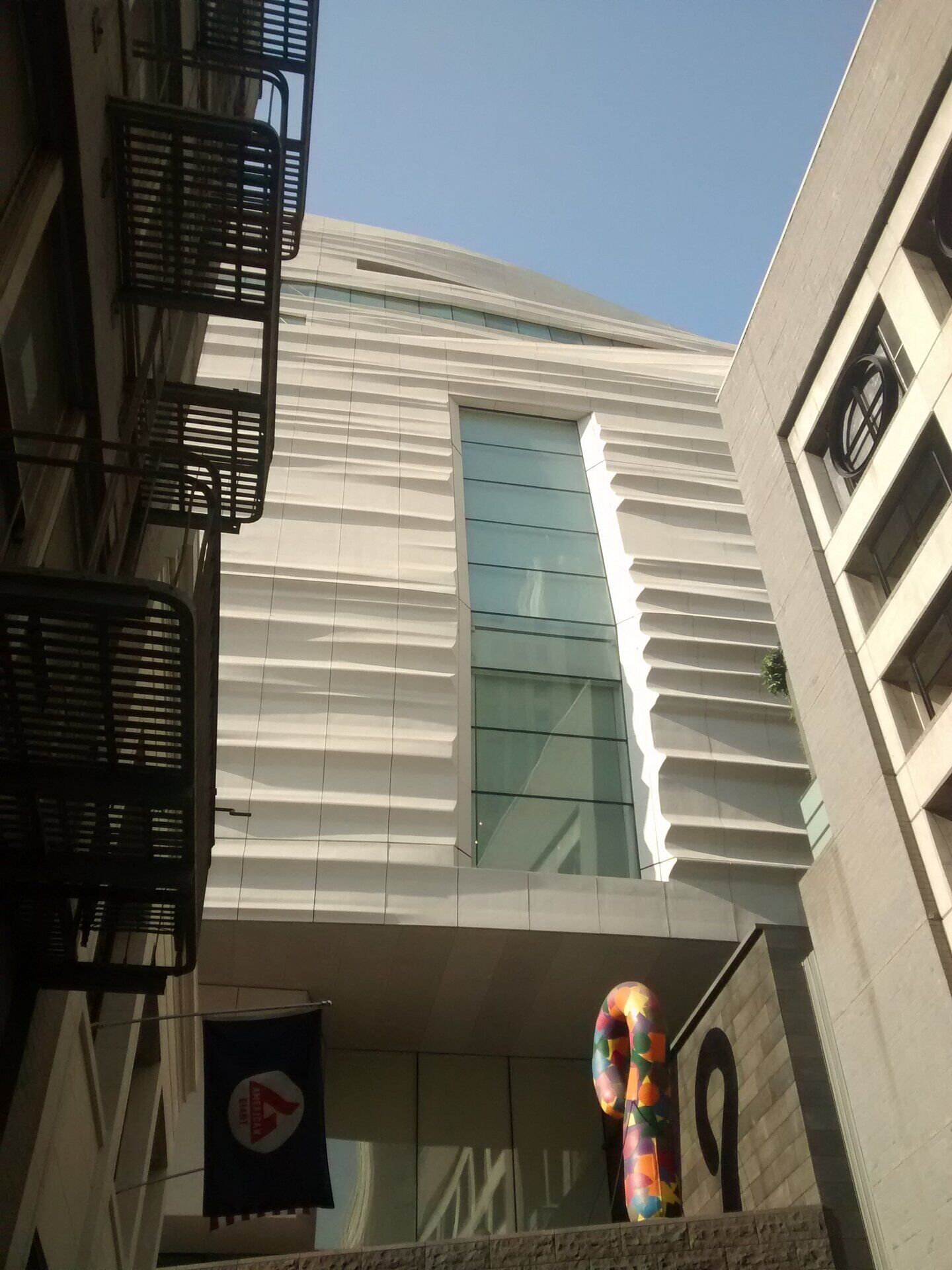

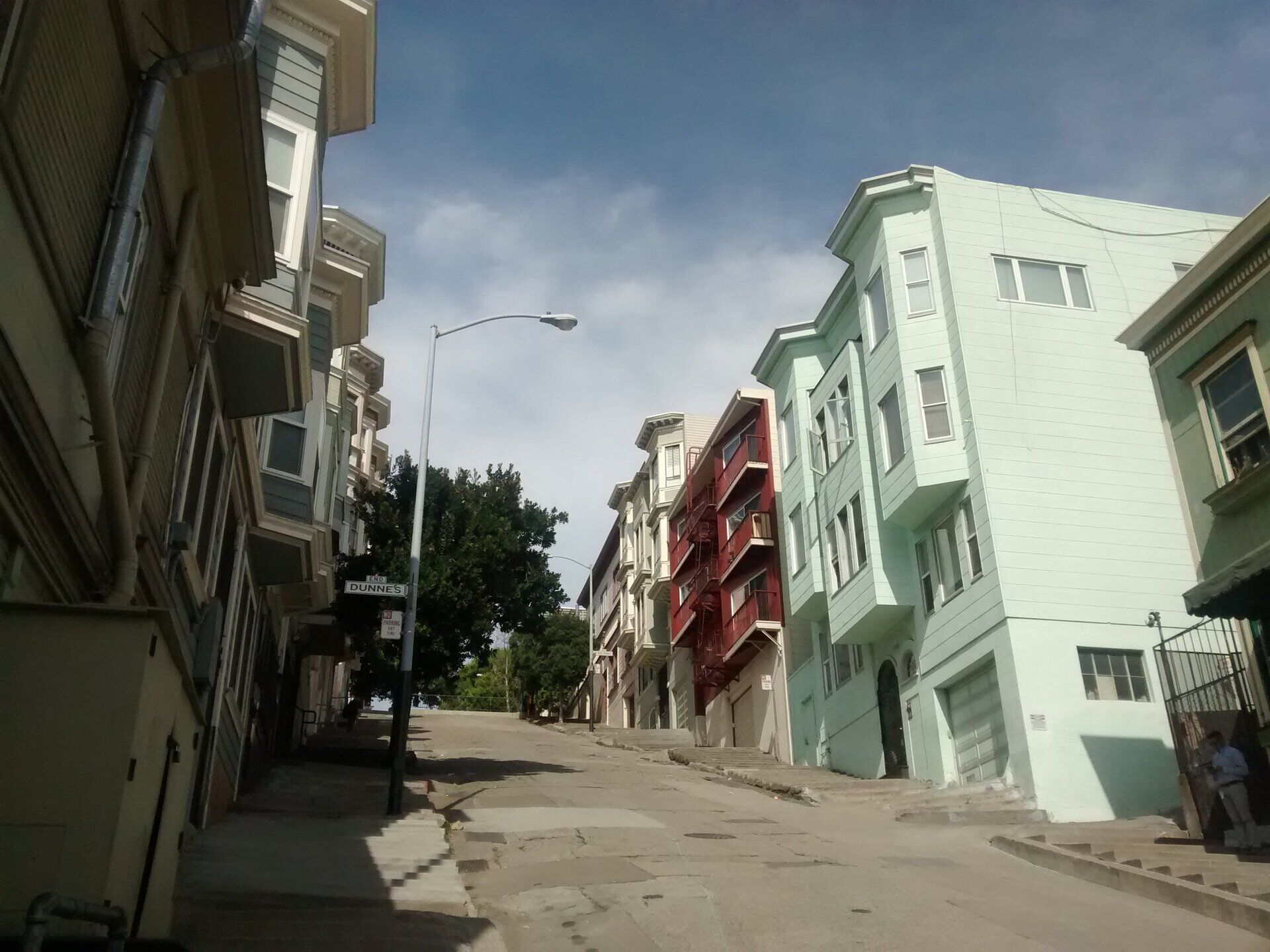
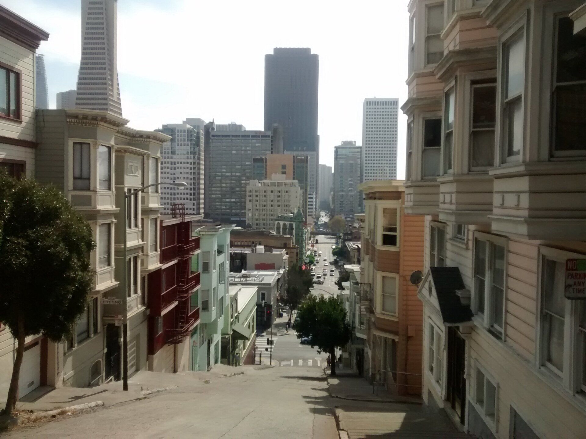
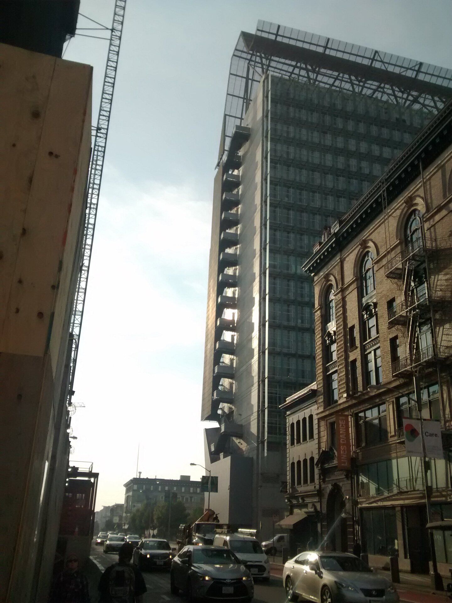


Telegraph Hill

Fisherman's Wharf

Union Square

Federal Building

The Embarcadero

Jewish Museum

Twin Peaks


Just wanted to say this article was really well written and covered a lot of ideas I have been considering as well.
William
FreeCAD Arch development news - September 2017

Hi everybody! Here we are for another monthly report about the development of BIM tools for FreeCAD, our favorite open-source 3D CAD modeling platform. The coding I am doing for FreeCAD is now more and more heavily supported and funded by many of you via my Patreon page, thanks once more to everybody who contributes to this, it is incredibly motivating. We won't stop until we get a proper open-source, multiplatform BIM modeler!
WikiLab
As expected in last month report, this month I had very little time to dedicate to FreeCAD coding itself, because our WikiLab project construction started, and it swallowed almost all of my time. I am saving the Patreon money of this month, though, and as soon as the WikiLab is finished (about two more weeks to go) and I'm back from the GSOC mentors meeting (see below), I'll be back at FreeCAD coding with full dedication and twice the money to spend (and I really miss coding already).

This time spent on the WikiLab is not lost at all for FreeCAD, though. First, the project were entirely developed on FreeCAD. The whole project files are open-source, hosted here. Check the two FcStd files in the main repo folder, one contains the base WikiHouse module, called "Wren", that file was used to generate the CNC cut sheets, and the other is the complete assembled model, that was used to generate the construction manual, documents for aproval, etc.
Second thing, everything happening during the construction (changes from the original project, difficulties, etc) is being recorded, documented, and is onlien on the same github account. There will be several reports written at the end of it all about the different aspects of the experience (technical, financial, etc..)
Also, the construction of a WikiHouse building is an amazing experience, and this is giving us a wealth of useful information, feedback, ideas. We used one of the main WikiHouse designs (the Wren module) almost without any modification, to stay on the safe side. However, we added many experiments around it, for example the "rain cover" that we're currently placing around it, or our hybrid construction model, part made by volunteers, part made by a professional construction team.

This all is too much information to be resumed here in a couple of paragraphs, but count on me to write detailed articles about all this after the dust settles. To resume a bit what's going on, the WikiHouse construction itself is a wonderful thing. People with no experience at all in building come, need only two tools (a rubber hammer and a flat screwdriver to "help" hammering the joints in), and in 2 hours everybody has turned into a WikiHouse building professional, able to build without even looking at the plan. There was no difficulty, no accident, and no "gambiarra". The result is very solid, while still manageable (the biggest parts, once assembled, can still be moved around by a 10-people team).
The rain cover is being built now, I'll have more to tell about it next month, but it is a very simple, cheap (whole cover costs less than 4000 BRL/1300 USD/1100 EUR), ansd easy to build solution. The polypropylene sheets we used can be cut with a pair of scissors. And they give a nice look (kind of cheap SANAA  )
)

The hybrid construction system, half professional, half volunteers works up pretty well to some extend, but it is the hardest part to manage. They are very, very different types of construction. The volunteers part is very, very fast, but requires everything to be very well planned ahead. The traditional system with a professional contractor, however, is slower, but they take care of a big part of the planning themselves, and there is much more experimentation and and on-site modifications possible. Really, both have their strengths, and I'm still very much convinced that it is a good way to go. But their different rythms are really hard to sync and "compatibilize", specially that we did this in three parts, first part with the contractor, second part with the volunteer team, and now the third part with the contractor again. This scheme should realy be simplified in the future.
Also one other thing stiked my mind, that I hadn't fully realized before: You don't make this with a team of volunteers to save money. You do it because people want to build their own house. The construction itself is the "product", not the finished house. The disappointment of the team when their "task" is over is big  In the future we'll need to find smart solutions that allow the team to stay on-site up to the very end.

Both the professional and volunteers teams also need very different kinds of documents. Professionals are used to architecture drawings, and they feel more at ease opening a plan, that has everything on a single sheet, than browsing through a book. However, the book makes the whole construction easier to understand by volunteers. If you have both kinds of teams, you need both.
Let's talk about BIM
This started from a discussion that I had with a friend this month, about "all that BIM stuff", and several other discussions I stumbled upon on the net go in the same direction, so let's sum some of it here, no doubt it's a subject all of use are interested in 
The basic point we started with was "What about all that fuss, BIM here, BIM there, at the end where is the big gain?" Everybody who works in a BIM-enabled architecture office has a lot to rant about. BIM makes project organization actually MORE difficult than before, BIM is just a commercial concept idealized by software vendors to make you pay more, BIM actually RESTRICTS creativity (Some things were avoided in your project because they were hard to do with the BIM software being used, don't tell me this never happened to you), collaboration works "more or less" when everybody uses the same software, but becomes so complicated when different software is used that you end up needing a "BIM manager" to sort things out, etc.
Compare this with the 2D-based era, there are clear steps back IMHO.
However, what we're trying to do goes beyond the mere BIM term. I mean having a project that is fully (and reasonably accurately) modelled in 3D, and that is organized semantically (this cuboid shape is a wall, that other is a beam, both belong to the same floor, etc), and that contains as much non-geometrical data as possible/needed (this wall is made of 20cm of concrete block with specific thermal and structural properties), so that model can be used in many ways (to generate drawings, to study structural resistance or thermal behaviour, etc). Basically, a model that can be understood and used by others.
When you tell all this to mechanical engineers they usually look at you like, what's the fuss, we're doing that since a long time, and we still call it CAD.
But there is something interesting happening now: More and more you hear or read similar opinions. And far from being something negative, I think it actually serves the general direction. Many BIM gurus are having new looks at IFC, the good, old, clumsy, ugly, all-in-one BIM format that everybody likes to hate. That format should already have died a long time ago, by commercial standards. However, not only it doesn't die, but many people are having a new go at issues like versionning (or this one) or, like in a previous article I wrote, parametric files. And more and more people are also using it (I think) the way it is meant to be used: controlled and validated by rules.
It turns out the good old IFC format, even being ugly and clumsy, has surprisingly more tools than previosuly thought to deal with these "advanced" issues. In the case of versionning, I also think that the problem is beyond the file format itself, versionning CAD/BIM files is a complex problem where a change can be significant for a machine but not for a human, and vice-versa, unlike code. So the problem is actually larger, and when you look deeper at it, the IFC format contains many stems and tools that could at some point give birth to realiable solutions. We'll probably need to invent a revision control system that is very much based on semantics too (a way to "tell" or "describe" what has changed in a model).
All in one, I hope all the "myth" around BIM is beginning to fail/die, and I think it's a good thing for BIM...
Survey
I've not been able to do much in FreeCAD this month, apart from a couple of bug fixes. But I managed to work on one feature that needed a bit of love, which is the Arch Survey tool. This tool allows you to quickly take a couple of measurements by clicking on a model, like traditional quantity surveyors would do on a plan, by measuring the lines.

Until now you had to sum things up yourself. Now, the tool has gained a proper interface that sums lengths and areas as you click them. So it becomes very easy to measure, for example, the total length of walls that you have, or the total area of concrete slabs. And the final result is exportable as a CVS file, that you can import in a spreadsheet.
There are many more possible improvements, be sure to add your voice to the forum thread!
GSOC
Finally, next month I'll be in the San Francisco Bay Area for the Google Summer of Code Mentors Summit. I'm really curious to see the inside of Google (Count on me to reveal all the secrets I'll be able to grab!), and it will be a great opportunity to meet the BRL-CAD people too, with who we're participating to the GSOC program for the second time, I hope we can set up more ideas to work together with other free and open-source CAD projects.
If you are in San Francisco around october 15-19, be sure to tell be and let's have a beer or coffee somewhere!
Urban sketchers meeting in São Paulo
4 days sketching through São Paulo with 250 people from whole Brazil and beyond...


FreeCAD Arch development news - August 2017
Time for our monthly development report, explaining a bit of what I did this month. Thanks again to everybody who help me on Patreon, each month we're getting higher! If you don't know about it yet, you can help me to spend more time working on FreeCAD by sponsoring me with any amount you want on Patreon. Some of you have asked me if it was possible to give me some money directly via PayPal, well it sure is! My PP email is yorik (at) uncreated (dot) net.
Bugfixing
This month however I will have much fewer to share than usual. There are two main reasons to this, one is that I've been doing a lot of bugfixing, which is too boring to talk about here. It is boring to do too, of course. Any coder will tell you that it is much more fun to develop new features than fix bugs. However, they are very important. The stability of an application depends heavily of the relentless testing, identifying and fixing of bugs.
I saw where FreeCAD comes from, and when you compare it with FreeCAD as it is today, even with all the remaining bugs and problems it has, the evolution of its stability has been phenomenal. All thanks to this: tiny bugfix after tiny bugfix...
There is a story I always like to tell about bugs. We architects are usually very sensitive about errors. Doing a mistake is a terrible thing for an architect, and results in huge blame, shame, guilt. You always try to show that you know everything. As you can imagine, this also comes with a strong tendency to hide the dirt under the carpet.
When I began to work with Jürgen and Werner on FreeCAD, it is one of the first things that surprised me much: How these guys treated their own errors as a normal thing, a bug. Bugs happen. You are human, you make mistakes, the same way as you breathe or eat. It wouldn't make sense to feel guilty for this. Since then, I always try to treat architecture work like that too: Consider your mistakes as a normal part of what you produce, try to make them appear (unit tests for architecture?) so they can be processed and fixed.
Jürgen and Werner and all other FreeCAD developers, if you guys read this, thanks! I am learning a lot with all of you.
Draft Scale UI
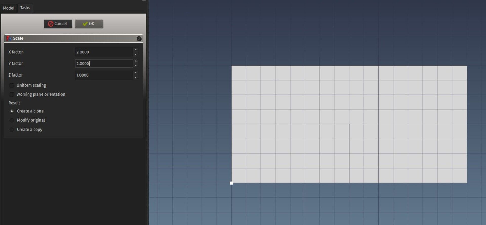
One of the things I did that was really sorely needed is a better User Interface for the Draft tool, that was really clumsy (you needed to "indicate" graphically the scale factor). Now there is a simple, proper dialog to scale things up/down, which allows you also to choose the result: Scale the original objects or produce a Draft Clone (where the scale can be changed later).
WikiLab
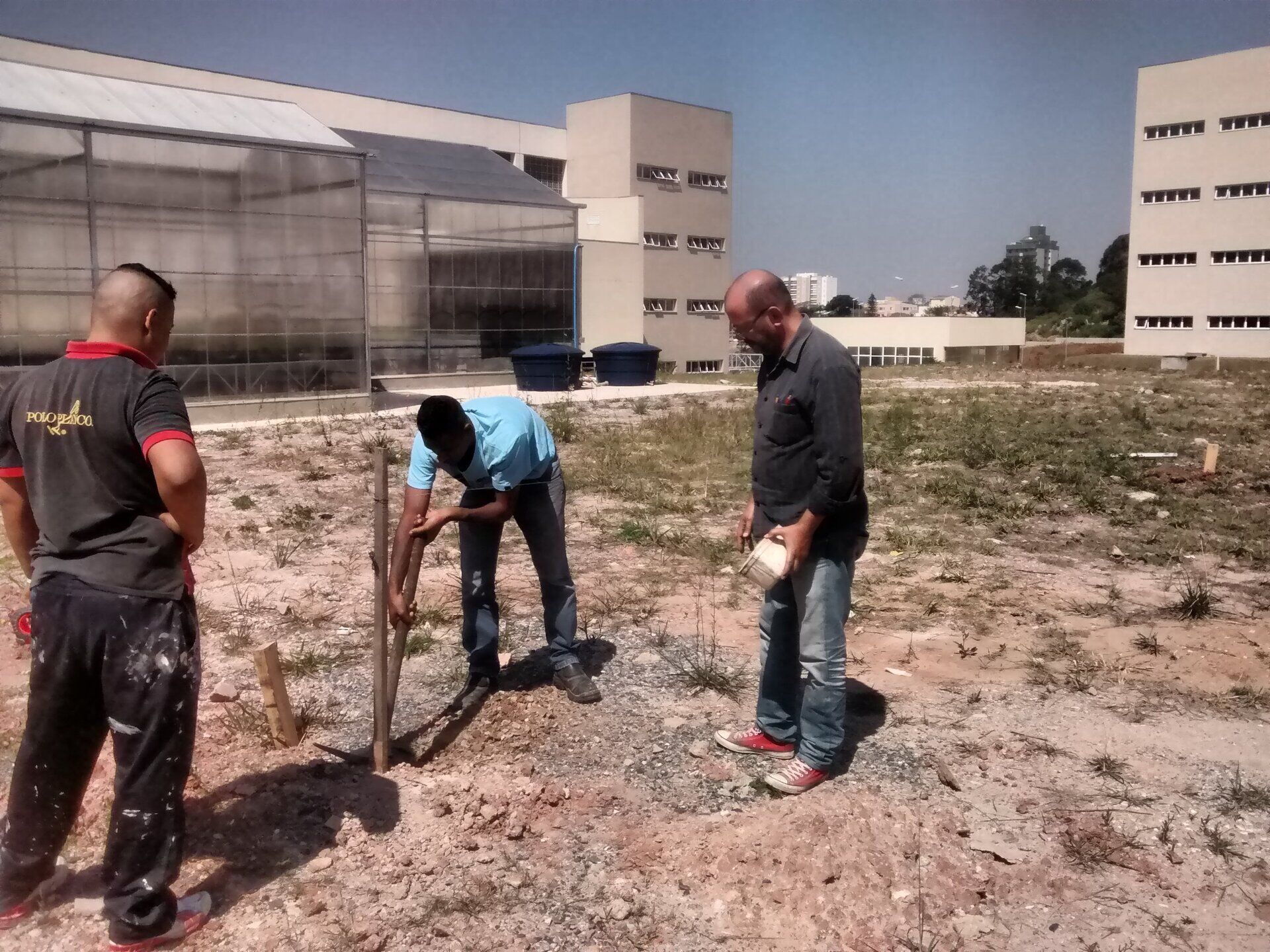
The other reason why this report will be less interesting this month is that the construction of our WikiLab project has started yesterday, so I simply had less time to work on new FreeCAD stuff. There has been quite a lot of work to do these last weeks to have all the construction documents ready before construction start, and the approval process ended up not being as smooth as we thought either (it is actually not entirely finished...).
But all this is also not work for nothing. The main issue with approval is, as you might imagine, fire resistence. Our WikiLab is made of wood, which burns. The risk for human beings is extremely low (the room is very small, only holds a few people, is escaped very easily, nobody will sleep there, etc), and the OSB panels we are using already have a slower buring rate because the glue they are made with acts as a fire retardant, but the problem is that there is as of today very little official record of all this. People in charge of approval basically want to see a document that guarantees them that such wall will hold a certain time under fire. These documents don't exist yet, because people rarely build walls with OSB panels, so panels manufacturers have little interes to pay for the research and fire tests needed to obtain such guarantees. Plus, these tests are very specific, so in our case a fire test would be valid only if it was made with the exact same wall composition as we are using.
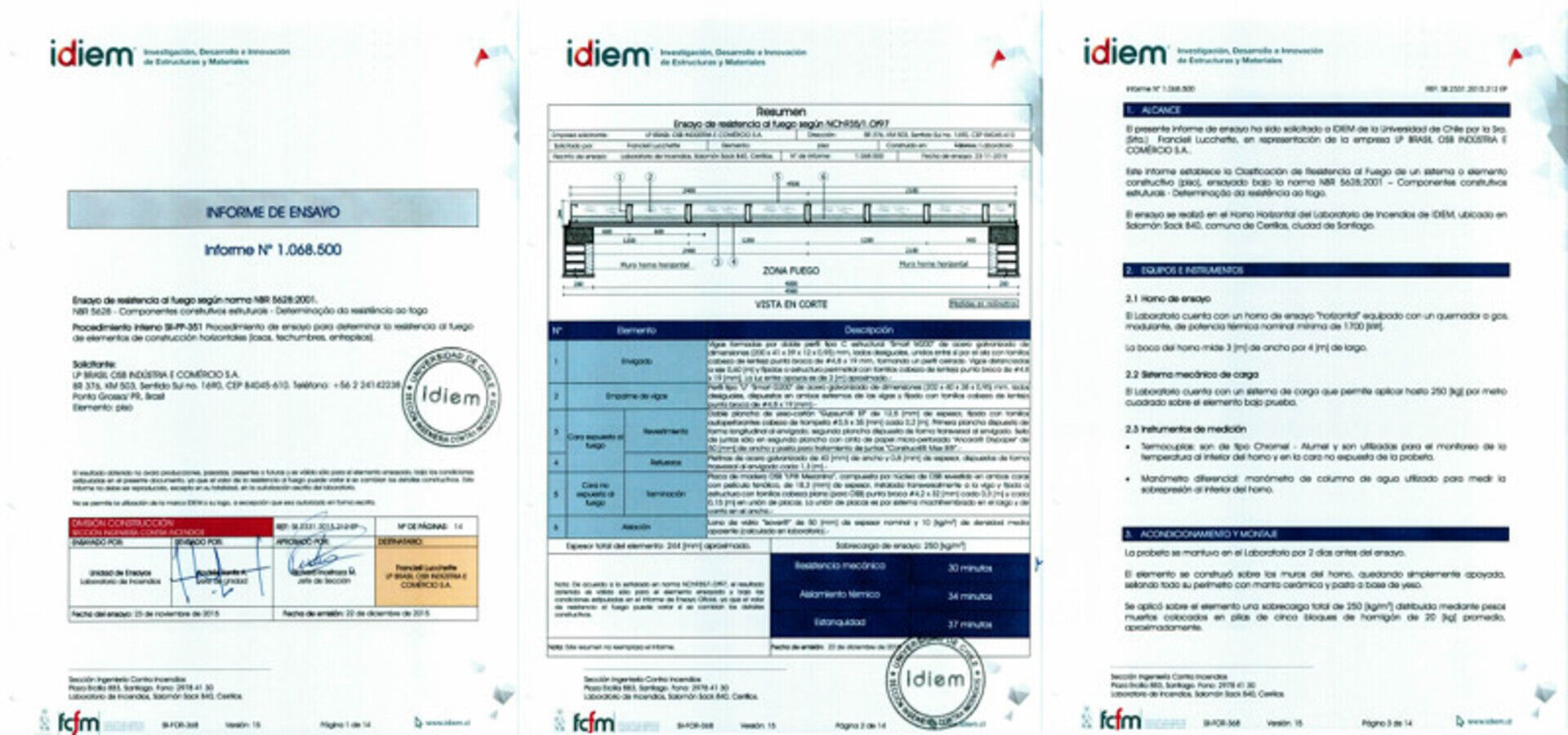
This is a well-known problem when using experimental systems. Convincing authorities is very hard. But that is also where this process is interesting and useful, when done, we will have created a precedent, which will lower the difficulty for all subsequent ones, because they'll be able to refer to this one.
Coin-based views
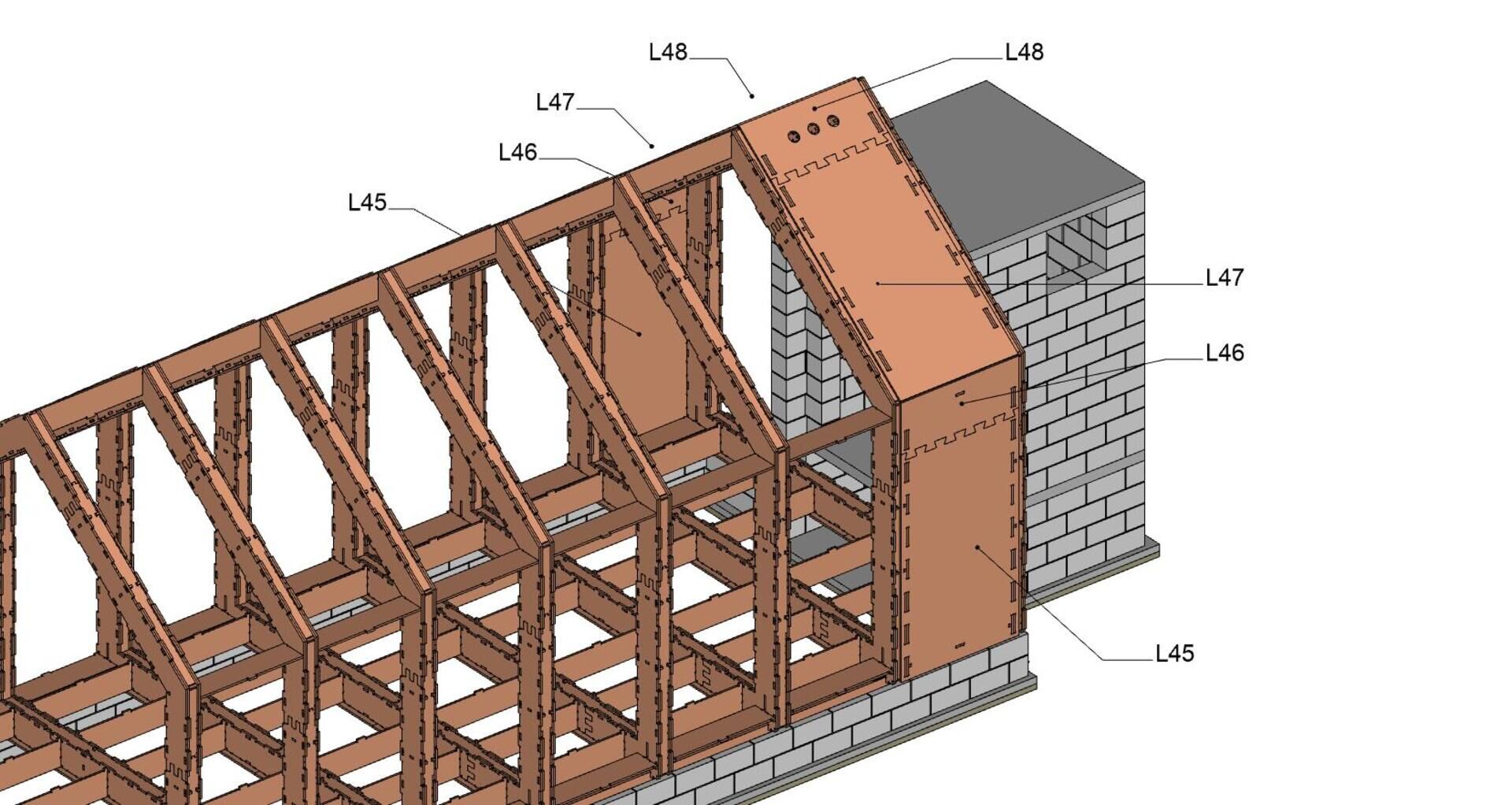
The work on the WikiLab construction documents also allowed me to play further with another idea I had: The 3D view of FreeCAD is pretty nice: It is anti-aliased, line style, width, thickness, color, transparency are configurable by object, it has a nice support for fonts, and even things like transparent textures. So instead of the heavy ans slow workflow needed to produce "traditional" 2D views with the Drawing or TechDraw workbenches, you could simply grab a nice view of your 3D window.
So far these cannot be exported "as is" to vectorial 2D. Exporting a 3D view to PDF is supported by the Coin3D engine (which powers the 3D view of FreeCAD), but the result is often buggy, the engine struggles at rendering some complex 3D situations to PDF.
However, exporting a 3D view to bitmap formats usually works very well. Most architects who will read this might dismay in horror at the idea of exporting architecture work as a non-vectorial format, but there are many "but" here.
First, it makes sense of course to export your work in a CAD format, such as DXF or DWG if others need to work with it. But a PDF? Will anyone ever import a PDF to work on it in a CAD program? That would be pure masochism, there wouldn't be much you could do with it. Also, when working in an open-source way, or any case where your base files are more easily acessible to others, and are in an open format, all this discussion looses a lot of its meaning... If a person can get a FreeCAD file, why would that person need a PDF file 
The next advantage of a vector-based format such as PDF is the reduced filesize. However, this is true for basic line-based work, but as soon as you use more fancy things such as transparency or textures or gradients, most CAD systems will turn that into bitmap anyway, so much for the file size. And large complex areas filled with one color can often be smaller in size in bitmap than vector format, where havy triangulation is needed (which by the way often stays visible in the PDF file). So there is not much difference at the end.
The third advantage of vector-based files is that you can zoom in and things continue to look sharp (this is certainly only useful for on-screen viewing, has any of you ever printed a PDF file at higher scale than 1x?). But this is just a matter of resolution, just save an image with enough resolution to be well readable when zoomed a lot, and this problem disappears. Plus, even if your image is embedded in a PDF file, zomming is blind-fast compared to zooming vector-based PDF files.
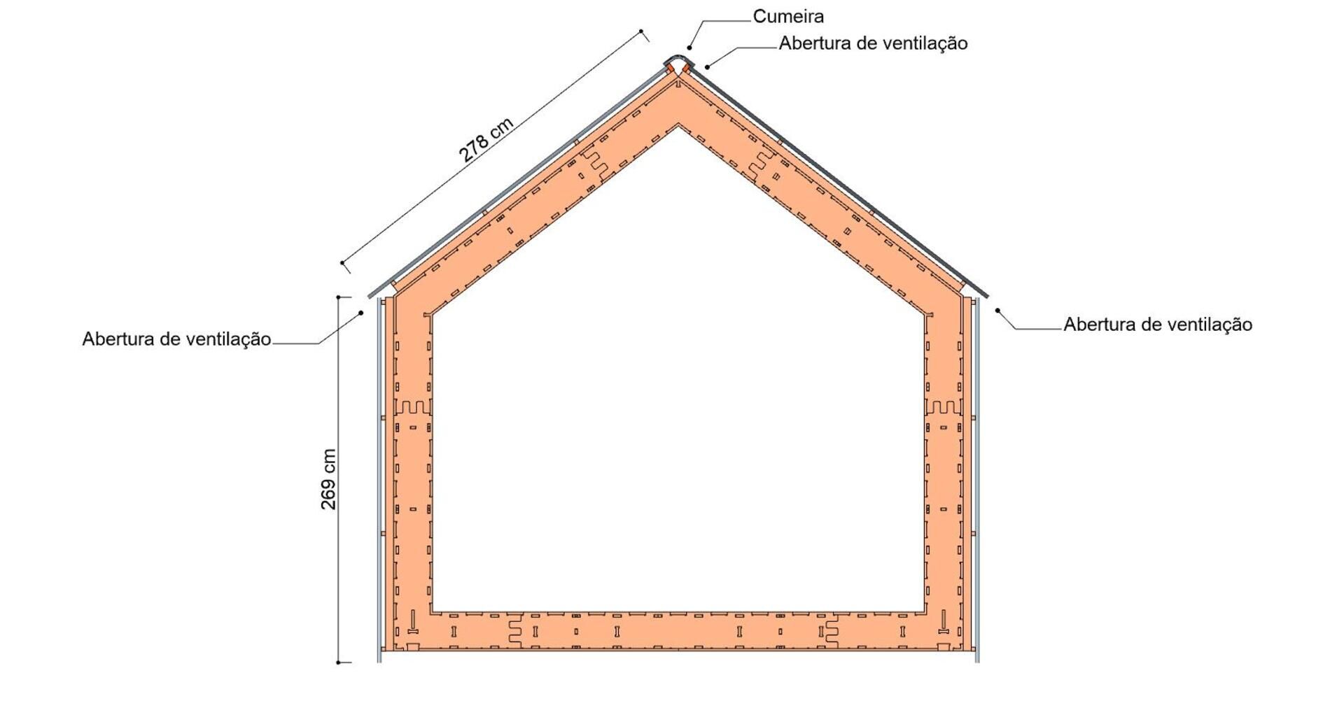
In the last years I've used bitmap files more and more to show traditional CAD work like floor plans. You can do all kinds of fancy things in Photoshop Gimp, and if you manage your layers well, it is totally manageable to reimport a layer from your CAD/BIM app when something changes in the project.
So I used this a lot in these construction documents. By using Working Plane Proxies you can easily configure views that you can recall anytime, so it is easy to produce a new image that is identical of the last one when the project has changed. And the Tools->Save image dialog of FreeCAD allows you to save an image with a very high resolution, which gives a very sharp result.
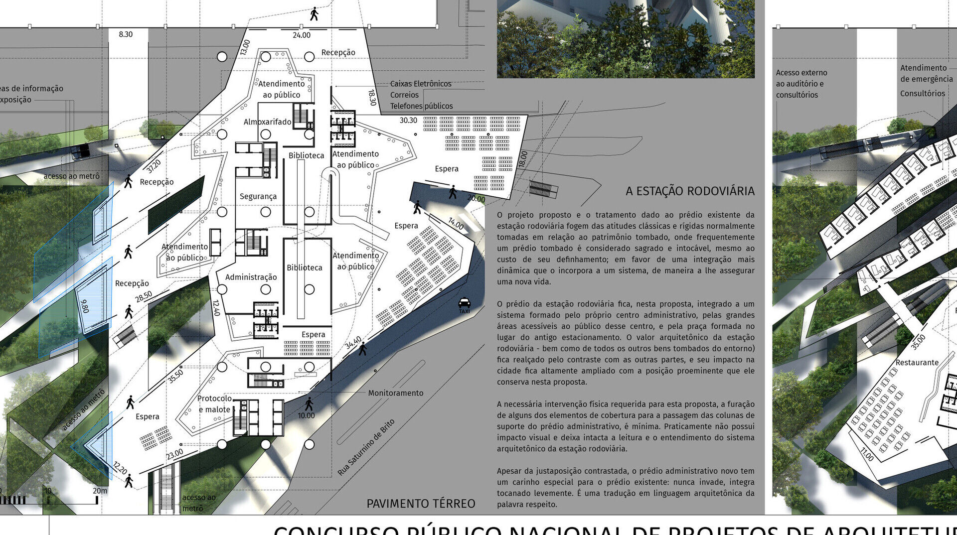
There are sill issues to solve, such as calculating the resulting scale, or ensuring that texts and dimensions have coherent and consequent size across different views, but that shouldn't be hard to solve.
Of course this is not the holy grail. There is still a series of situations where you'll need vector-based output. But when you try to show a project in different ways, like we did here, it might become a lot more convenient.
Arch Grid
The only real new feature I've been working on this month is the Arch Grid, that I just merged. A tool to construct a grid object, like you do in a spreadsheet: define columns and rows, change their sizes, and merge cells together.
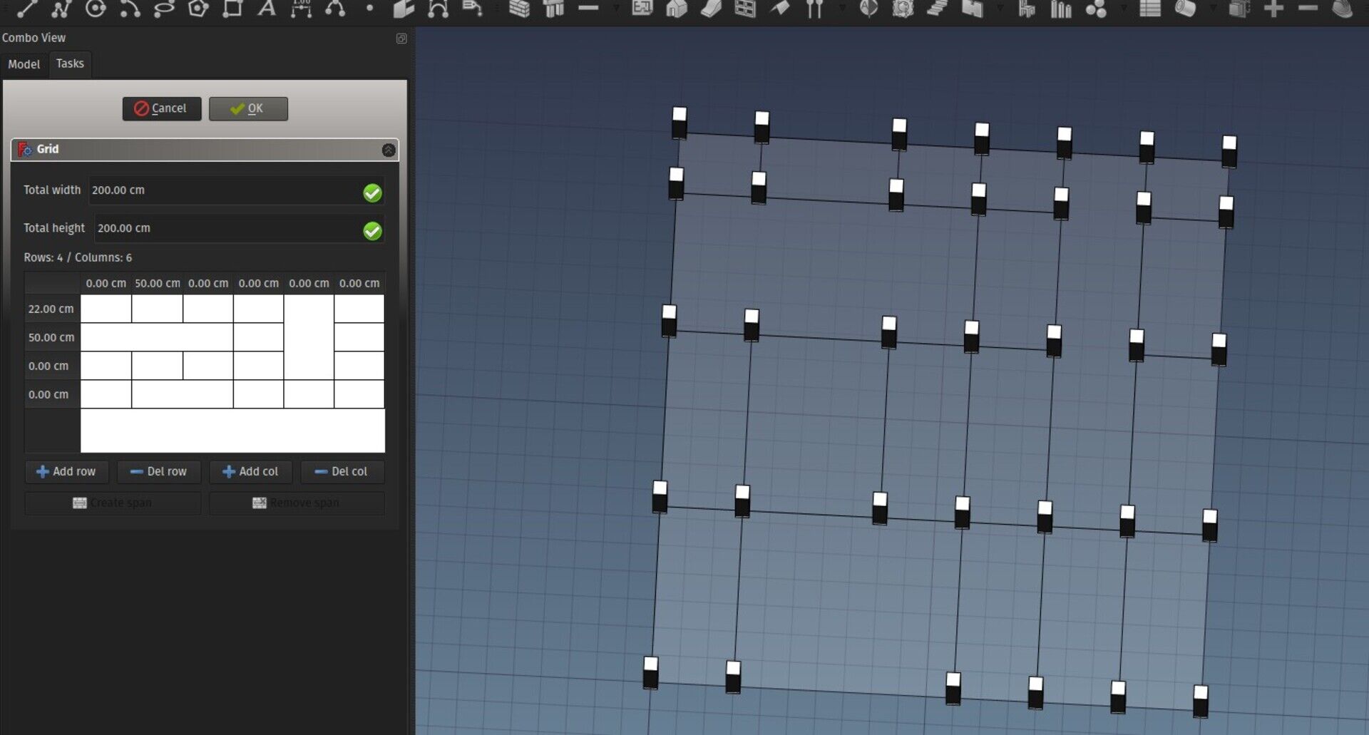
This object can then be used to perform a series of other operations with Arch objects, for example spread objects on its vertices, face centers or edge midpoints, or use it as a base for windows, instead of a sketch, or for any other kind of situation such as constructing railings.
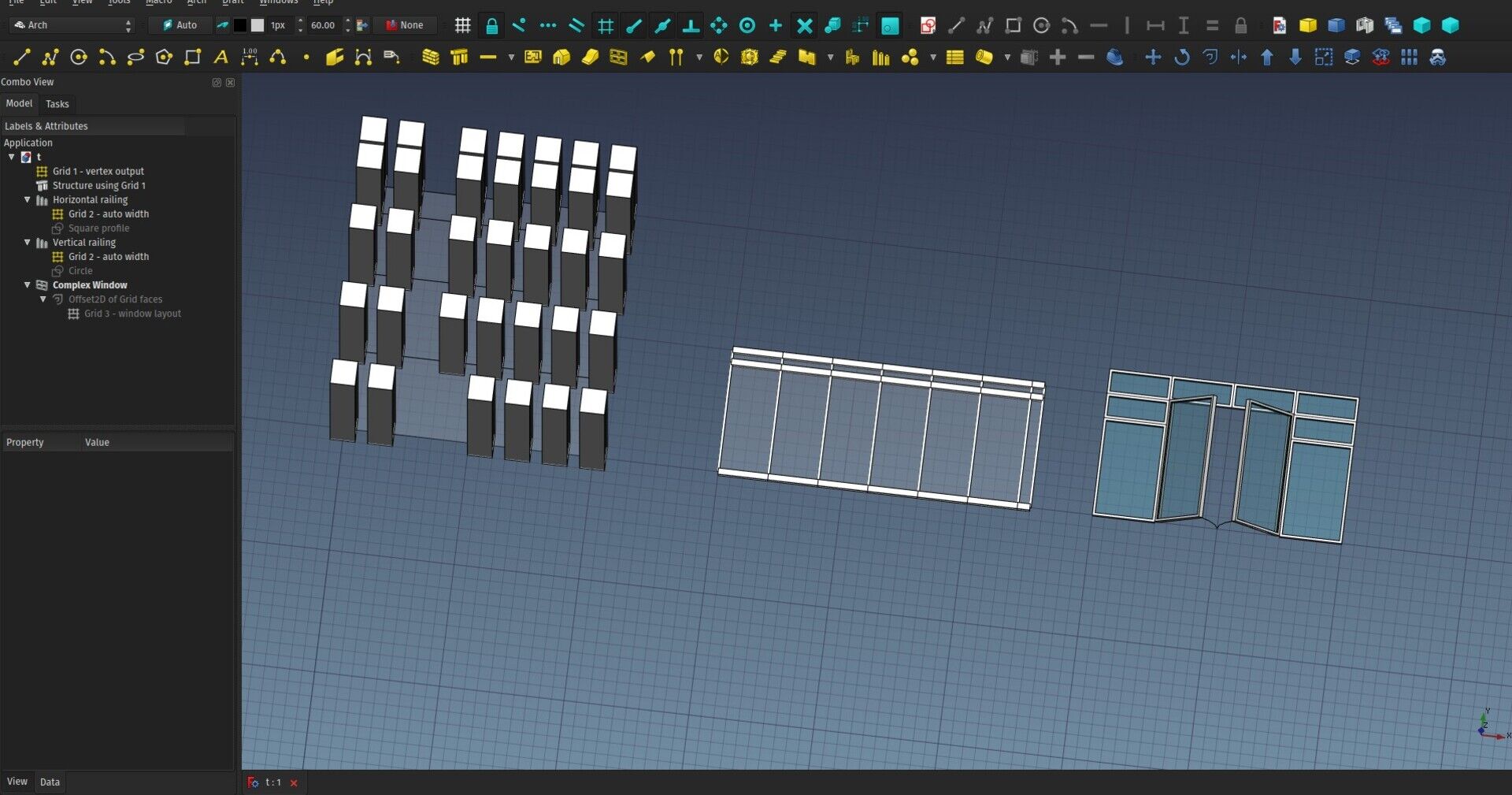
Download that test file here (you might need to wait a bit, because I just committed the change)
That's it for this month I'm afraid, sorry I couldn't do more, next month will likely be like this one too as we will be building the WikiLab, but you can count on me to share all I can during the construction. Almost all our wooden part are cut and ready to be assembled, the masonry base is being built now, and the assembly is scheduled to start on september 12th. If you are in São Paulo at that moment, don't miss the opportunity to participate!
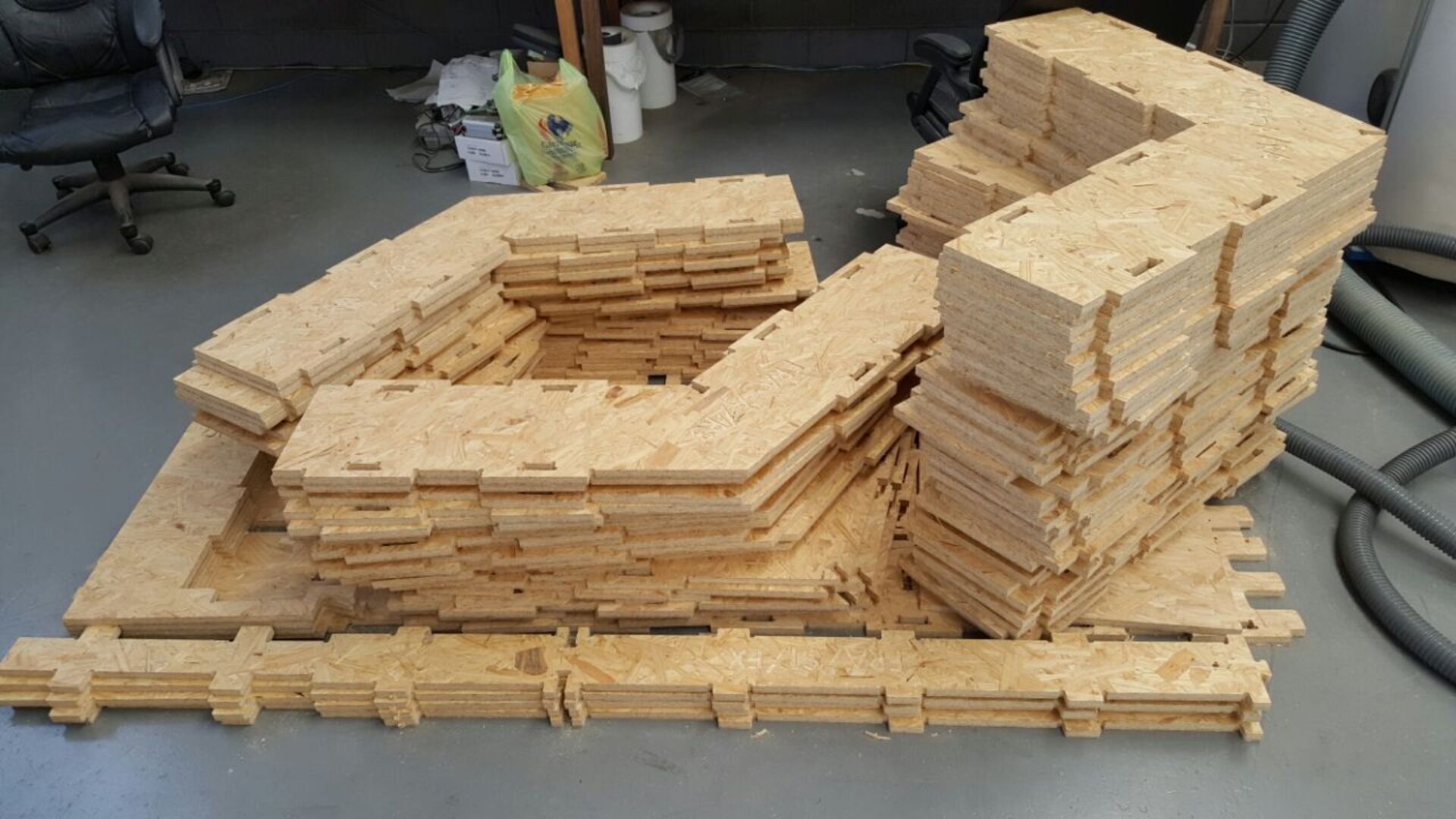
Thanks again to everybody who is helping this adventure to come true, each month a step closer to a full, feature-rich open-source BIM application!


About parametric IFC files
The title of this article sucks, I know, couldn't think of anything better...
This is a concept I wanted to play with since a long time, and last month I was finally able to setup a proof of concept. The only missing part was to write an article explaining it, so here it goes.
For who is not familiar with the BIM or parametric 3D world, IFC is a file format used to exchange BIM data. BIM stands for Building Information Modeling, and is basically "3D parametric modeling for the construction industry".
There has been quite a fuss for a long time on the internet about this. "IFC is not parametric", you'll read around. "So it cannot be used to transmit model intelligence", Revit users (and specially sellers) will tell you. This always annoyed me... After all a file, that is stored on your computer, is a "dead" thing. It cannot perform computations, it's just a storage for data, so how could it be intelligent? There is no such thing as an "intelligent file format" except maybe in the mouth of some astute marketing gurus...
The "intelligence" doesn't lie in the file. It is the application that does intelligent things with the data it finds in the file. Also consider what a parametric object is. A parametric box, for example, would have 3 parameters: Length, width and height. A program would then construct a box geometry from these 3 parameters. The 3 parameters are everything that is needed for the program to construct the box. If you save these 3 parameters to a file, when reading the file back, the same program will be able to reconstruct the box, just knowing its length, width and height.
I'm using in this text words like "parameters" or "attributes" or "properties" more or less indifferently. It means basically, a piece of data (number, text, whatever) that is attached to an object, for example the length of our box.
This idea comes from an old discussion I once had with Inkscape people. Inkscape uses the very well-known and very standardized SVG format, which is readable by a huge amount of applications, including almost all web browsers. The SVG specification is something tighly maintained and controlled by the same consortium that maintains HTML and almost all the web standards.
However, Inkscape needs to save things in its files that are not part of the standard SVG specifications. They do this by writing standard SVG files, but adding custom properties to standard objects, which is something the SVG specification allows.
So Inkscape, when reading that file, will see the custom properties, and be able to use them the way they are meant to, while other applications will simply ignore those properties, and will only consider the standard parts.
An example of that is the "star" tool of Inkscape. The star object created by this tool is parametric, that is, if you edit the star after you created it, you will still be able to modify the number of spikes, the radius, etc. If you save the file, and reopen it, you are still able to change the number of spikes.
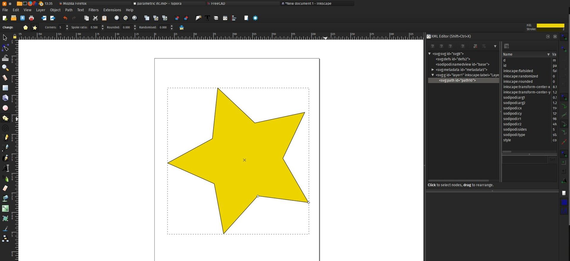
If you open that same file with any other SVG application that is not Inkscape, they will show the star correctly, but won't be able to edit it. Inside the file, the object is a standard SVG path object like this (the data inside the d parameter are point coordinates with instructions such as Movement or Line) :
<path d="M 100,100 L 90,75 L 100,95...">
This is standard stuff, readable by any SVG app. Inkscape adds its own attributes like this:
<path inkscape:type="star" inkscape:sides="5" inkscape:cx="90" inkscape:cy="95" d="M 100,100 L 90,75 L 100,95...">
"inkscap:sides" or "inkscape:type" are additional parameters that only inkscape will see when reading the file. Inkscape wil then know that this path is actually a star, and will be able to re-generate a different path data if you edit the star.
It was thought right from the start that applications might want to add such custom content to their SVG files, and therefore the SVG specification provides this nice namespace system where you can write your custom additions by preceding them with a name that identifies your application (inkscape: in this case), which turns it easy for you, the Inkscape developer, to identify Inkscape-specific content in the file. If you use such namespaces, the SVG specification even forces you to add a line like this in your file:
xmlns:inkscape="http://www.inkscape.org/namespaces/inkscape"
So other developers, when reading your file, when they see your inkscape: attributes, will not need to google for it, they will be able to go right to a page where you have carefully documented it all... Isn't that nice?
So basically here we are: the same concept can be applied to IFC. IFC supports adding custom properties to any object. Let's say you have an application that draws chocolate walls (yes, it's a BIM app for cake makers). You could make your application save your cake as an IFC file, and store its walls as standard IFC walls. But you would add a special property, for example: chocolate_type="milk chocolate". Your cake would still open in Revit, but only your app will see and read and use the chocolate_type property and will be able to recreate the cake faithfully and parametrically (you will be able to change the chocolate type after loading the file).
So I added this to FreeCAD, as a very simple proof of concept. There is now an option in Edit -> Preferences -> Import/Export -> IFC named "Export full FreeCAD parametric model". When you switch it on, when exporting to IFC, the resulting file, instead of being formatted like this:
IFCWALL (made from extrusion)
 ->   EXTRUSION (made by extruding a base polygon 2m high)
  ->      BASE POLYGON
Now contains additional properties like this:
IFCWALL (made from extrusion, and using 'FreeCAD' property set)
 ->   EXTRUSION (made by extruding a base polygon 2m high)
  ->      BASE POLYGON
 ->   'FreeCAD' PROPERTY SET
  ->      PROPERTY ObjectType="Arch.Wall"
  ->      PROPERTY Width="20cm"
  ->      PROPERTY Length="200cm"
  ->      PROPERTY Height="200cm"
See the full IFC file here, and the originating FreeCAD file here
The IFC importer of FreeCAD has also been adapted so when reading that file back in FreeCAD, you obtain faithful, 100% identical parametric objects as when you exported it. In fact, when FreeCAD finds an object inside an IFC file that has a "FreeCAD" property set, it will simply skip all the rest and reconstruct the object only from the contents of the property set.
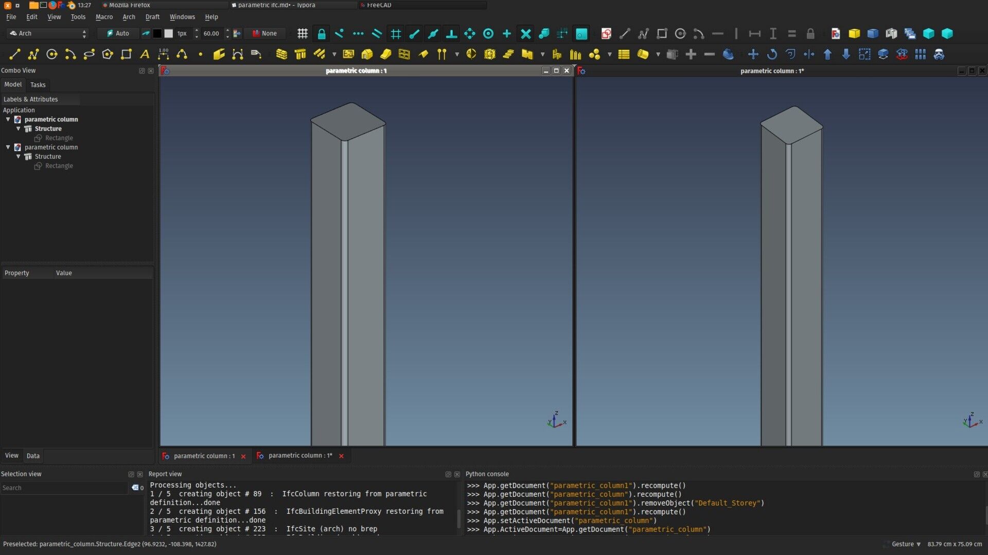
But other applications, unaware of the FreeCAD contents, will still see the "standard" definition:
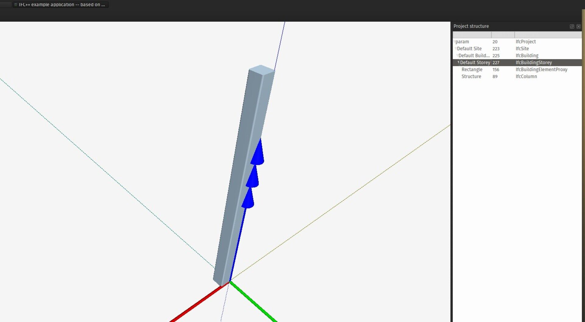
So far this is just a proof of concept. There are many property types of FreeCAD that are not yet supported. But it would not be much work to extend the system to support them all.
Now I can hear the arguments against all this gathering in your head. What's the point, if other apps won't be able to do anything of that shit? What if the other app modifies the standard IFC content, but leaves the FreeCAD property set intact? FreeCAD will ignore the modified version. Etc, etc. The counterarguments are many.
However, the discussion has shifted. What if such "extra" parameters/properties/attributes were clearly documented somewhere? What if, for example, Revit would export its walls with a defined set of properties that would allow it to recreate the wall 100% as it was before exporting? We could make FreeCAD see, use and modify those properties too. Or, even better, have a common definition that says "all walls must have length, width and height properties". That actually exists up to some very basic point in IFC, you can add a "standard wall property set" to walls, that contains such generic properties that should be common to all walls. I have never seen that system being used very much yet, though.
So is the problem not in defining things correctly, instead of blaming IFC for not being technically fit to the task? The model works well for SVG, it would be really worth trying...
Jon Mirtschin, the famous IFC guru behind GeometryGym, experimented a lot recently with similar concepts. The difference with his approach is that he found a way to bind properties to certain values in the IFC file. Simplifying a lot, his file looks like this:
IFCWALL (made from extrusion)
 ->   EXTRUSION (made by extruding a base polygon by the value of "Height")
  ->      BASE POLYGON
 ->   PROPERTY SET
  ->      PROPERTY Height="2m"
So the relationship between the extrusion value and the Height property is written in the file. This is obviously a much more interesting solution freedom-wise. Everything is stored inside the file. You can invent any kind of parametric relationship like this. And when you remember that GeometryGym is developed principally for Grasshopper, where you could read that file and reconstruct any kind of wild, crazy relationships written in the file (for example: The height of the wall equals to half the width of the whole facade, minus the height of the front door), this makes a lot of sense.
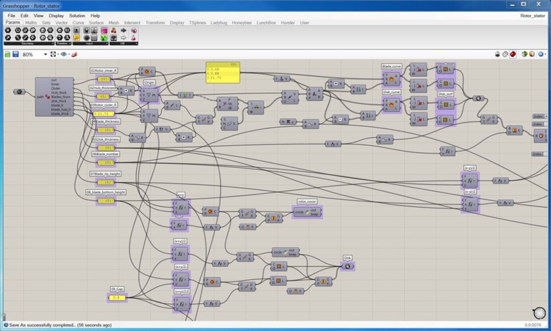
But the question remains: What would Revit do with a file that contains a definition like: "The height of the wall equals to half the width of the whole facade, minus the height of the front door". I think that's something where both approaches meet the same issue: Sooner or later, some of the parametric content will be discarded by some application, that will say "Here we don't construct walls like that. We don't allow this".
But my point in this article was to show this: Not only IFC can perfectly well contain parametric objects, it can even as Jon's example shows, contain your wildest parametric dreams, actually probably far beyond any other proprietary file format out there can do. Implementing parametric relationships in the IFC file format is something that has been researched for quite some time already, and there are other further plans too.
An IFC file that can do the full round-trip (be exported from your application and reimported with 100% faithfulness and all its "intelligence") is totally possible, that's now clear and proved. The remaining problem is actually not a technical issue, but much more a communication issue.
What if the consortium behind the IFC format would issue a chart, with things like "The parametric properties that a wall should have", or force you, if you add custom properties, to provide an URL where you explain it all, like SVG does? These things would not make the problem solved tomorrow, but would allow to progressively structurate and consolidate parametric IFC files, that could progressively become fully editable by more and more applications.


== John ==

FreeCAD Arch development news - July 2017
WTF, July development news in August, I hear you yelling (it's not only me!) But there was some last minute topic I really wanted to complete to include in this report... But now that it is complete, I think it deserves another post on its own, so I'll only mention it here briefly. It will be worth it, I swear 
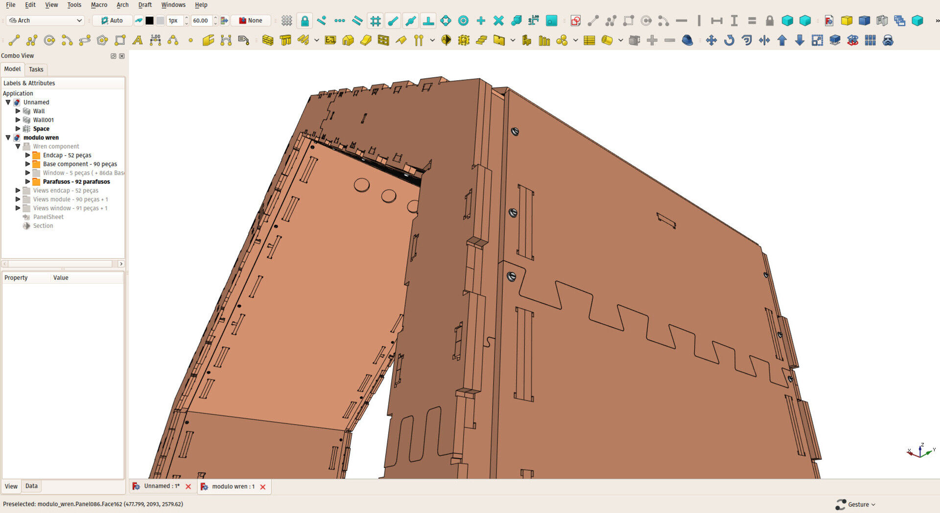
First off, I'd like to thank once again everybody who is contributing to my Patreon campaign and through there helping me to spend more time working on FreeCAD. This month I passed over USD 500/month, which becomes pretty important. In Brazil, where I live, the "official" salary of an architect (that is, recommended by the national council of architects) is around USD 2500/month. In reality, only some architects working in public institutions earn that much, in the private sector the usual salary is about half that amount. To put things in context, the 10% bar, that is, the salary you must earn to be in the richest 10% in Brazil is around USD 1100. So my 500/month begin to represent some consequent weight (it's almost a teacher salary). Yeah, these things make you think a LOT about what value is. And for who.
I started this Patreon campaign not really knowing where it would go and if it would allow for something serious, but now I begin to really believe it can change a lot. Working half-time as an architect and half-time as a FreeCAD coder is an idea I'm growing really fond of...
But enough about me, there is quite a lot to tell this month.
Parametric IFC
This is the big thing I wanted to merge before writing this report. I'll post something more detailed soon, but the idea is basically to export all the parameters of FreeCAD objects to IFC. So when reimporting that IFC file in FreeCAD, parametric objects are fully and faithfully restored. The idea is to show/prove that yes, IFC is totally adapted for parametric design. More on that very soon.
Nester
So the big thing I have been working on these last months is now merged in FreeCAD. I have been posting about it in the previous report already. It is an algorithm that organizes shapes to fit into a containing shape. This is useful in CNC operations, when, for example, you want to cut out a series of wooden pieces out of a wood panel, and want to stack all these pieces the best possible way on your panel.
There is now a nesting tool in FreeCAD, located in the Arch workbench, under the panel tools:
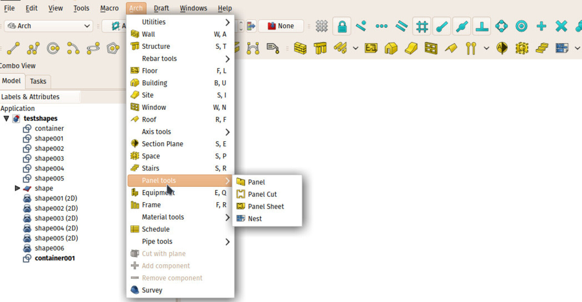
The system is simple, you launch the tool, select the containing object, then add the objects to be placed inside. Tune some parameters if needed, and launch the calculation. It is currently not much optimized and quite slow. When the calculation has finished, you can see a preview of the result, and if you apply that result, the object get moved and rotated to their preview position.
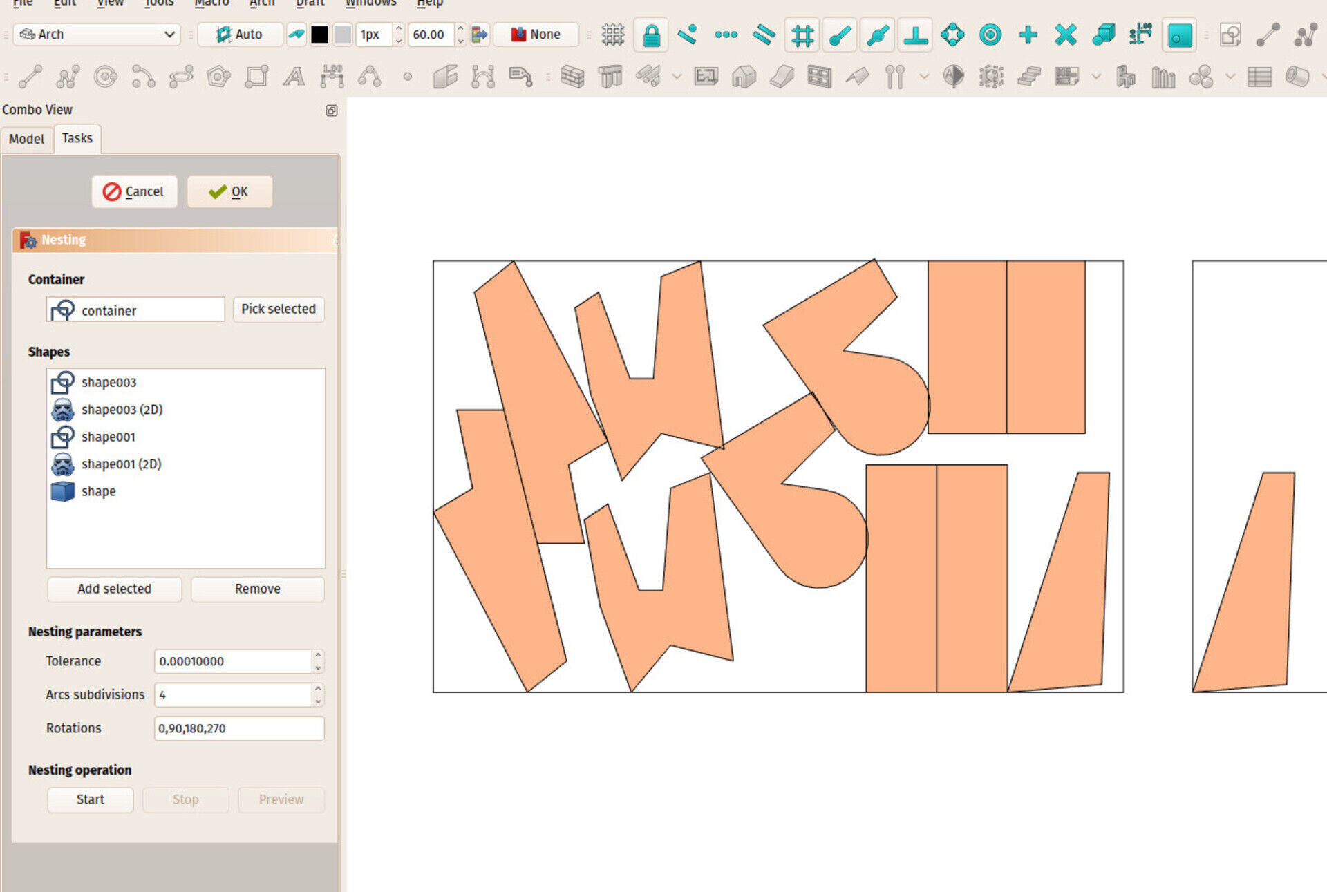
The next two features I'll add are support for margins (you usually don't want te pieces to touch, but leave a certain margin between them) and allow for non-rectangular container, so for example you could reuse scrap material easily. Then it'll be time to attack some optimization.
The nesting algorithm itself is separated from the tool above, so it could be used differently by other tools and workbenches. And also, it can be recoded in C++, which should make it run a lot faster. That will be done too later on.
New axis behaviour
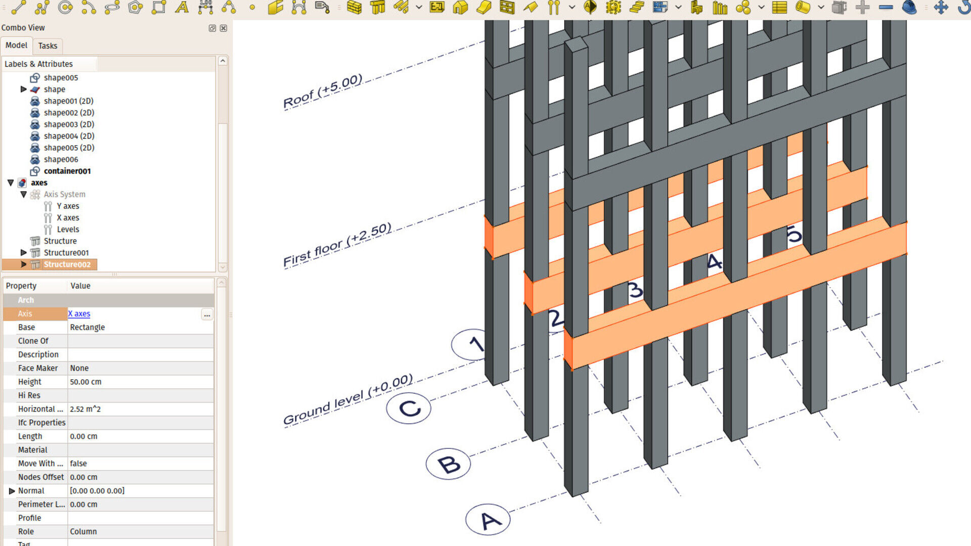
I also introduced several changes to the Arch Axis system. There was already a way to make a series of structural objects spread over the crossing points of different axes, but it was not very easy to find and weird to use. I believe the new system is much cleaner and powerful. It basically works like this now:
-
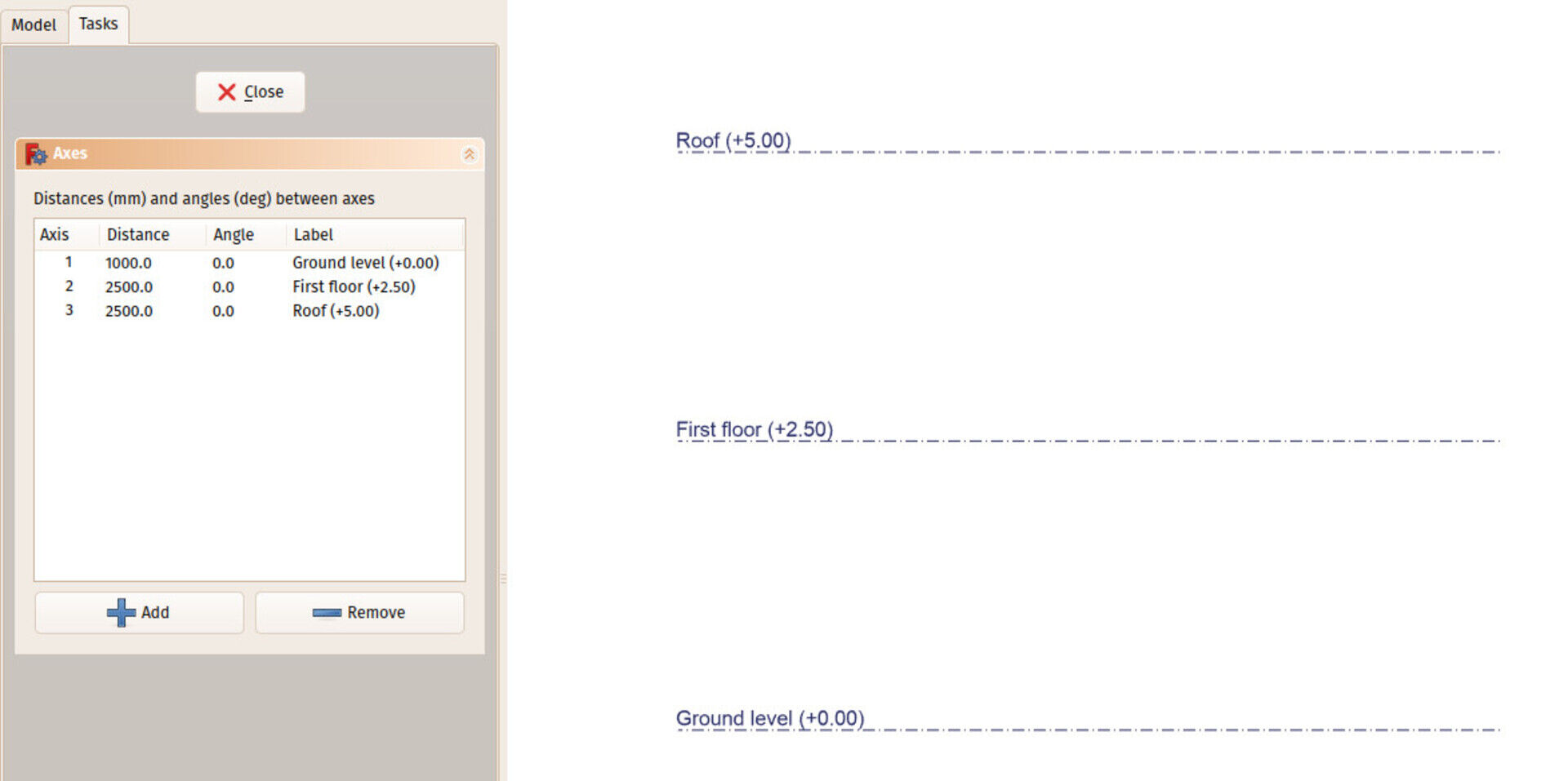
The old Axis System tool is still there, it has simply been renamed to Axis. It has a different icon (
 ) and it still does what it did before, that is, it creates a 1-direction series of axes. For example, all the A, B, C axes.
 - That tool has also gained a couple of extra features: You can now give it a series of labels, one for each axis, that can be displayed next to each axis (you can fine-tune the position). And you can turn the bubble off. This allows to use the axis for many different scenarios, such as indicating levels.
-
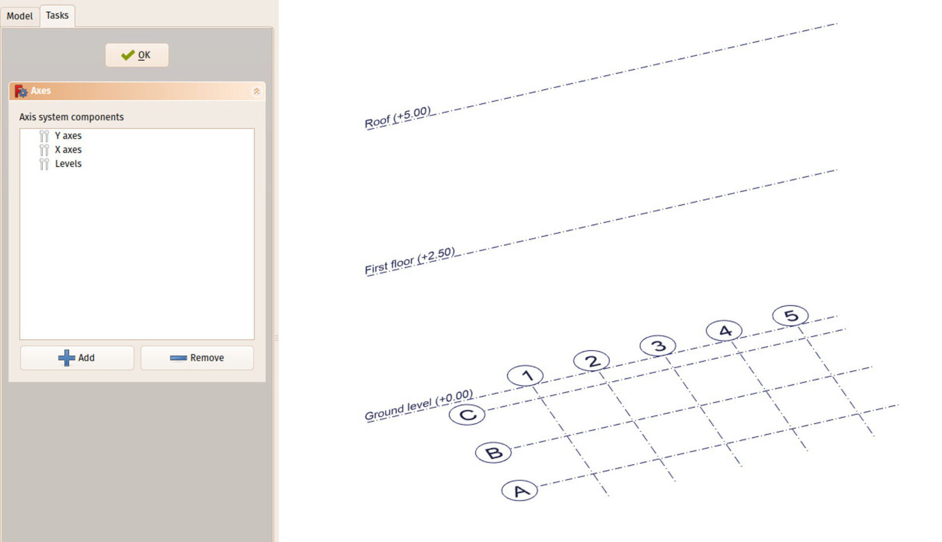
There is now a new Arch tool, called Axis System that now really does what the
 icon means: Organize several axes series into one system. It can take two or three axes objects (you can edit that by double-clicking the axis system in the tree). Its function is basically to calculate the intersection points between all the axes.
-
Not only structures, but all Arch objets can now be spread along axes or axes systems. For that, they gained a new Axis property. By setting this property, you can make your object be duplicated automatically. The rule is as follows:
- If the Axis property points to an axis system, the object will be duplicated on each intersection point of the axes in the system
- If the Axis property points to a single axis, the object will be duplicated once on each axis
- Otherwise, if the Axis property points to any Shape-based object, the object is duplicated on each vertex of that shape.
Now I think the situation is much cleaner, it's much easier to first create your axis systems properly, then make your other arch objects make use of it, and change/undo all this whenever needed. Also,by using any other shape as an axis system, many wilder possibilities become possible, such as using a sketch to drive the position of Arch objects, etc.
Working Plane Proxy enghancements
The Draft Working Plane tool is something you use constantly and everywhere when working with Arch. It is one of these tools that grew more and more complex over time, and that is now quite a powerful behemoth... For who is not used to Draft/Arch, it is responsible for setting a 2D plane where all the subsequent Draft and Arch operations will take place. The location of this working plane is represented by the Draft grid, that shows the position and orientation of the plane, and also gives a visual interval (the grid size), which you can also snap to.
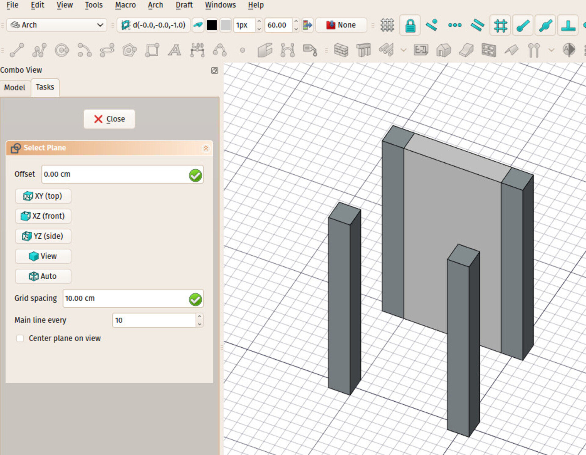
The current possibilities are fair already, you can set that working plane quickly to one of the origin planes (top, front, side) or select a face and make the working plane adopt that face orientation and position.
Now I added a new Working Plane Proxy tool in Draft, that stores the position of the current working plane. It is represented on screen by a small widget (the size is customizable).
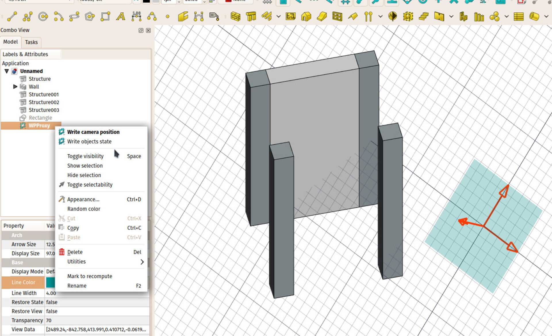
When selecting this widget and pressing the working plane button, the working plane will return to the location/orientation of the widget. You can even move and rotate the widget by conventional ways (it has a Placement).
The idea is that you can now save important working plane positions in your document, precisely, without the need to have "real" geometry there.
This proxy object also has two more interesting features: a Restore View property, that will, when restoring the working plane to the proxy position, also restore the camera position. So you can use the proxy object to store not only the position of the working plane, but also the view angle. You can change/store the current view anytime to a proxy object, by right-clicking it in the tree.
The other feature is a Restore State property that, when restoring the working plane, will also restore the visible/invisible state of all document objects (the ones that were present in the document when storing those states, that is). Here too, you can store the current state anytime by right-clicking the object.
With these two features, we are paving the way for a more conventional BIM environment, where you can switch from working on one floor to another floor, and all your environment (working plane, view orientation, visible objects) will change accordingly.
Next thing I'll look at is how to tie that to Floor objects, but these floors need a good refactoring first...
Rebar / non DAG workaround
The recent GSOC work on Arch rebars (I strongly suggest you to have a look at the impressive work being done by Amritpal, our GSOC student, and several members of the community around, the image above is taken from there) also gave us the opportunity to tackle a long-lasting inherent design problem of the Arch workbench, the famous non-DAG bug. DAG stands for direct acyclic graph. It describes a type of graph or tree which all flows in the same direction, where it is forbidden to go backwards. The relationships between objects in a FreeCAD document is a DAG.
That means the dependency chain between FreeCAD objects must always flow in the same direction: You can object C that depends on object B that depends on object A, but you cannot have object A that depends on object B that in turn depends on object A. That would be a cyclic dependency (you cannot know which one comes first, A or B) and is forbidden in FreeCAD (if you find yourself in such a situation, FreeCAD will print non-DAG error messages and refuse to process anythingmore until you fix the problem).
Two Arch objects were constantly creating non-DAG situations: Windows and Rebars. The window, for example, often depends on its host wall (in order to know on which face it lies) and the wall also depends on the window to know how to drill the opening where the window is placed. The workarounds I had imagined until now to circumvent the problem were really not very satisfactory (for example create a second wall, so the base wall and the wall with the opening were two different objects).
With the Rebar, we now experimented a new idea that seems to solve the problem for good. It is not the "parent" object that knows which "children" it holds anymore. It is the child that knows which "parent" it belongs to, and the parent is not dependent on the child anymore.
That introduces a bit more complex system: The wall doesn't know which window is part of itself anymore, so when updating its geometry, it now has to "scan" the scene to find the windows it must use to drill openings. But this is a very ponctual and unperceptible slowdown, and I think totally worth the much cleaner situation and the vanishing of the dreaded non-DAG problem.
The Rebar object already uses the new system, and it seems to work very well, so I'll adapt the window to use the same system in the coming days.
Cabinet design
Another talk I had with a FreeCAD user (that will soon become a more stucturated plan) lead me to this interesting experiment, where you take a simple Part Box, and use it as a "driver" shape for inner objects, like the panels and doors of a cupboard. This is an interesting workflow, and I liked to be able to work with simple boxes, that contain their own more detailed components.
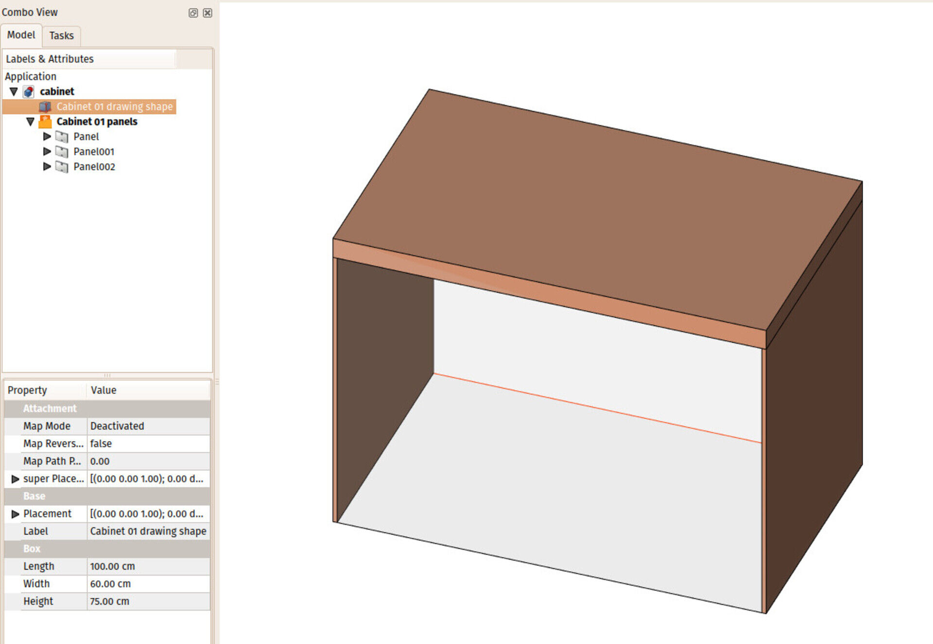
The test file is here if you want to have a look at how it works.
I already had other discussions before about furniture/cabinet design with Regis and others, it would be a good time to think about a proper workbench for it.
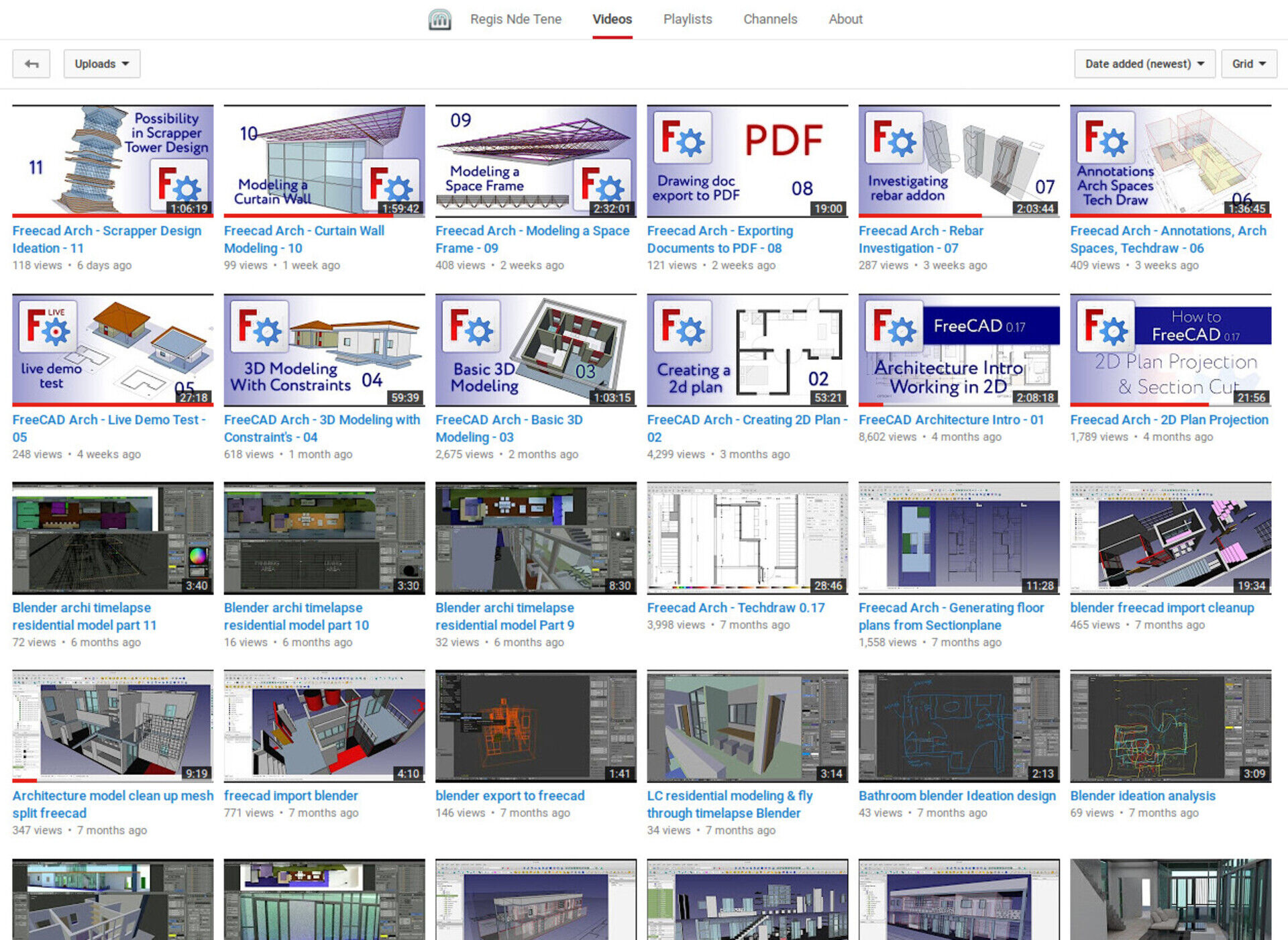
Talking about Regis, one of the most knowledgeable Arch/BIM FreeCAD users around, have a look at the impressive series of videos he has been producing lately about BIM work in FreeCAD...
Arch space bounds
I also added UI controls to edit the boundary objects of Arch Spaces. Spaces can be based on a solid object (their shape is therefore the shape of the solid object), or a set of boundary faces (the shape of the space is therefore the bounding box of all these faces, subtracted by the volumes - or half-spaces - behind those faces), or a mix of both (the shape of the space is the shape of the base solid, subtracted by the half-spaces behind the boundary faces).
There was until now no way to edit the list of boundary faces without using the python console, this is now solved.
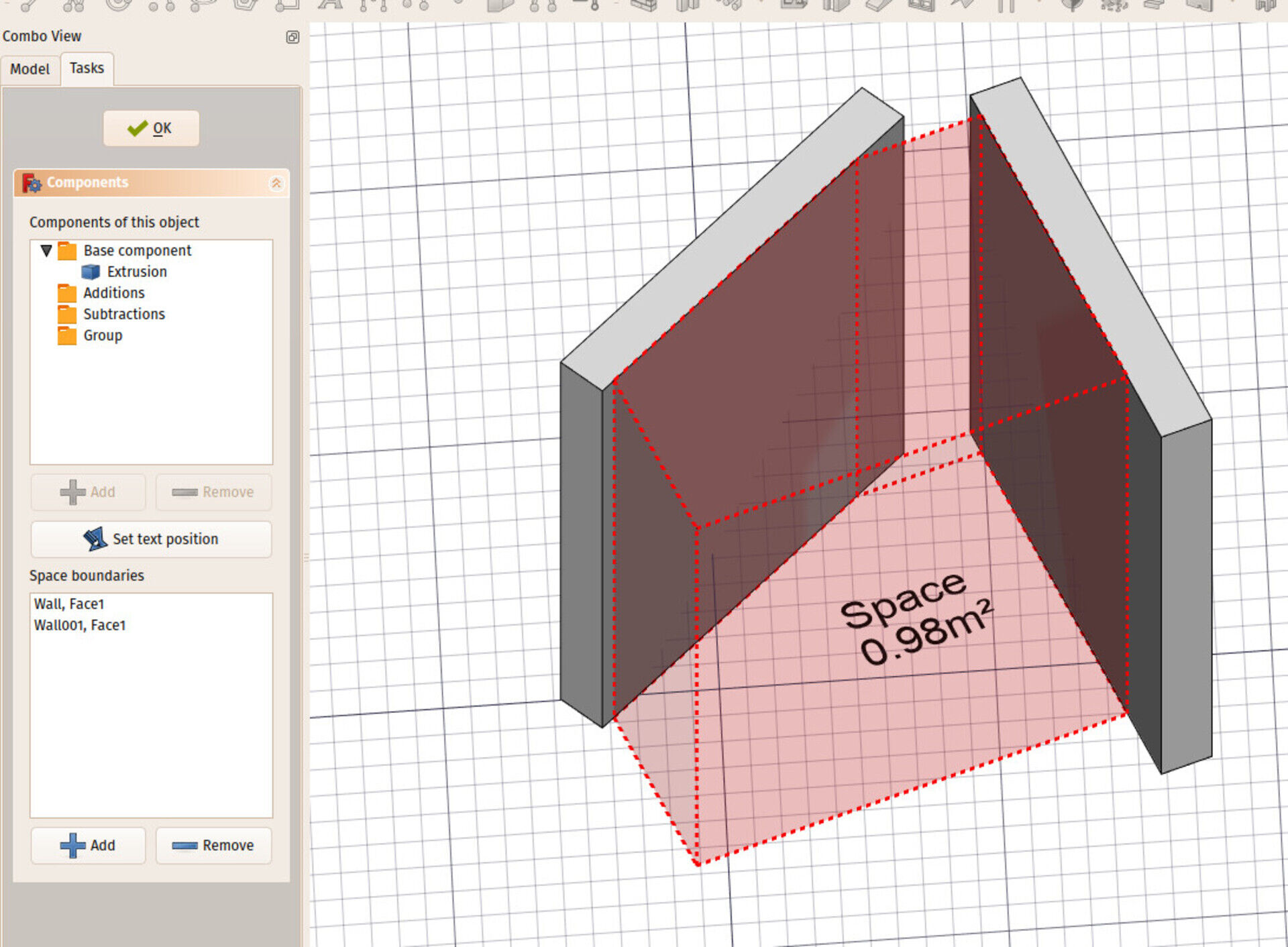
That's it for now, sorry about posting late! Still a lot that I wanted to do this month that will be for the next month, but step by step we're getting there. Thanks for reading, thanks to everybody who help me to make this come true, and as always, comments are welcome!


This is not so easy unfortunately, you cannot just take a script written for one application and make it run on another, even if they are written in the same language. It would take days or weeks and might be even easier to rewrite from zero.
It might be easier/more fficient for you to work in Blender, no?
I am amateur interested in the history and the immitation of citadels and old castles built in stone and brick
And as I want models with details cornices, bow, pilaster, ceiling, etc.
I try to write a macro for freecad
For this I find a program written in python to blender:
Add_mesh_masonry.py written by Paul Spooner
Can you help me to make it compatible with freecad especially with the architecture workshop of freecad
Thank you in advance and here is the code:
##
#
# add_mesh_masonry.py (c) 2007 - 'til now; Paul Spooner (Dudecon)
snipped (...)
#
# optimize for speed. Make it run faster?
# Grout model... yeah.
# consider removing wedge crit for small "c" and "cl" values
# wrap around for openings on radial stonework?
# auto-clip wall edge to SMALL for radial and domes.
# unregister doesn't release all references.
# repeat for opening doesn't distribute evenly when radialized - see wrap around
# note above.
# if opening width == indent*2 the edge blocks fail (row of blocks cross opening).
# if openings overlap fills inverse with blocks.
# Negative grout width creates a pair of phantom blocks, seperated by grout
# width, inside the edges.
# I was going to add an "inner/outer" toggle for steps and shelves but user can just rotate 180

# though you can't set shelf and steps on opposite sides of wall...
The desktop is fluxbox (yeah I'm old-school but I really like it), with a theme I did and modified a bit afterwards to match the gtk theme base color, the gtk theme is elementary dark, the icon theme is Surfn Numix, the background I don't remember, and the geany theme is made by hand, just editing the filetypes.common file.

I don't know the first thing about FreeCAD, but when I saw your screenshot I instantly fall in love with your Geany (and GTK) theme. Could you possible share what themes do you use (and where can I get them)?
Thank you very much!
Gergő
blendercam.blogspot.fr/
A bientôt
FreeCAD Arch development news - June 2017

Hi all,
This is time for a new review of what has been going on in Arch development this month. Quite a lot actually, it's exciting that several things I've been working on during the last couple of months begin to flourish into pretty interesting and usable features.
There is another interesting thing happening, is a very good synergy between the WikiLab project I'm working on now, which you must grow tired of hearing about, and FreeCAD developement. FreeCAD fuels the project development, which in turns fuels FreeCAD with bugfixes and new features. Me and other FreeCAD community members are really keen to pursue and extend that synergy further with other projects.
As always, don't forget you can help me spending more time on FreeCAD, by sponsoring me via my Patreon campaign. As a side note, that campaign is really taking flight, sooner than I had expected, I'm highly overdue to update the campaign page, and add some whistles and bells such as goals and rewards.
As a possible reward, I am thinking about doing some short videos, explaining in detail specific feature of the Arch workbench, and more generally, doing BIM with FreeCAD. For example, one about walls, one about working with imported dwg files, things like that. These videos would be, in a first time, available to Patreon supporters only, as a kind of present to thank them, and then, after a couple of months, added on youtube for everybody. What do you think? Good idea? Lousy idea?
So enough of this, here is the real stuff:
WikiLab

If you are following the progresses of our WikiLab project, you might have seen that the crowdfunding campaign ended successfully, and we are now getting started. The wood panels have been ordered already, the final cutting sheets are being made, and the cutting should begin next week. This will take roughly two months, during which we will contract a constructor to build the foundation and base walls, and hopefully everything will be ready to build the WikiHouse-based part, at the end of August, during the university holidays, and just before the rainy season.
On the image above is a first "rib" we've been mounting this month, as a kind of proof-of-feasability, and to boost the crowdfunding campaign too. It went amazingly well, this element was built in about 2 hours by 5 people, it is very easy to understand and build, and the solidity is really impressive.
I'm also starting to write a manual (in portuguese) that willbe the actual construction document. No plans and sections in this project!
There are still several details to solve, some of them have been already discussed and solved on the WikiHouse community slack, which is a really cool way to solve these issues collaboratively, something we've been doing with OpeningDesign for quite some time already 


Last month I also had an online conversation with Harry Knight from the WikiHouse Foundation, and wrote an article on Medium.com about our project. Check it up!
We are also studying small changes and improvements to the design, such as holders for shelf supports, and ventilation holes at the top, that can be closed with 3D-printed custom lids.


Draft Label
This is a new feature I've been working on, inspired by Revit's tag objects. In Revit, you have different types of tags, that you can attach to an existing object. That tag will then automatically display a certain information about the attached object. For example, material tags will show the material of the object, door tags will show the door number, etc.
In FreeCAD I decided to go for a bit more generic approach: There is a new generic Draft Label object, which is made of a piece of text and a two-segment line, which can have an arrow at its end. The text can be made to display some property from the attached object. At the moment only a small list of properties are available, and can be selected from a drop-down box, but the system is very extensible and you could have those Labels display just any kind of information that can be retrieved from the base object.

As always, this is only the first, rough version, it works, but over time and use it will certainly refine ito something more solid and powerful. It should also gain additional feature so it can be used for all the Revit scenarios: show component numbers, space tags, etc. All these should be displayable in a distinct manner (in a rounded rectangular frame, in a circle, etc...)
Shuttleworth Foundation
The other big news of this month, is that I've been elected for a Shuttleworth Foundation Flash Grant! Thanks to OpenSourceEcology fellows, who indicated me! I still don't have fully formed plans for what to do with the money, but a couple of things I definitely want to do: 1) Help founding the wikilab project above (that is done already), 2) Turn the FreeCAD manual into a printed book. Most of the work is done already, it still needs a professional editor review, then it can be printed and sold, which nowadays is very easy thanks to sites like lulu.com. And 3) extend what I'm doing with the money from my Patreon campaign, spend more time coding for FreeCAD. I would be able to work half-time on FreeCAD for a coupe of months, I'm trying to see how to set that up now. As a point 4), I might have more/better ideas later on, still thinking about it.
GSOC / Rebar
This year, FreeCAD has received four student projects for the Google Summer of Code. For who doesn't know, it is a program by Google to sponsor students to work on open-source projects during the (northern hemisphere) summer months. We are now approximately at the middle of the coding period, and our 4 students are doing great!
I am myself mentoring one of these projects, together with Bernd, which is Amritpal Singh's proposal to extend the Reinforcement bar tools in FreeCAD's Arch module. So far so (very) good, Amritpal is surprising us with the quality of his code, which you can already test if using a development version of FreeCAD: Just install the Reinforcement addon via the addons manager, and on next run, the Arch workbench will detect it and add its tools under its current Rebar tool.
The objective of Amritpal's work is to extend the User Interface around the Rebar tool, to add it a series of tailored dialogs to create specific types of reinforcement bars, such as straight bars, U-shaped bars, stirrups, etc. All this UI work integrates with the current Rebar object, which is kept as the overall, can-do-everything Rebar object. The different dialogs help the user to create and edit these rebars in a more friendly way, but doesn't remove anything of the power of the base rebar object, which is simply made of a profile, an extrusion path, and a series of placements, and can therefore represent any kind of rebar we can think of.

Everybody wins with this approach: The normal user, who just wants a clear and easy way to add reinforcement bars, and the power user, for who these dialogs are not enough and who wants to tweak or script these rebars in any way possible.
Nester
Here is the best part, in my opinion. I'm working (it's not finished yet, but working already) on an algorithm to perform bin packing in FreeCAD. It is an operation that consists in placing/packing different shapes inside a container (the bin), so it uses as little space as possible. The immediate output, obviously, is toproduce cut sheets for WikiHouse-style constructions, like this:

Interestingly, this is a subject that renders a lot of theory (lots of research papers on the net), but few open-source applications. The only "readable" ones I found were SVGNest and the WikiHouse plugin for SketchUp. None of them is usable directly in FreeCAD (different coding language, too tied into their host system, etc), but they provided precious resource to understand how such an algorithm should work.
They both use the same concept, which is the no-fit polygon. The idea is more or less this: You place a first piece inside the container. Then, for each other piece, you try to "rotate" it around the already placed piece(s). You are basically trying to place the new piece as close as possible to the ones already there. By doing this, you end up defining a "no-go" zone, that is, a zone where our piece cannot go otherwise it would overlap the already placed pieces. By subtracting that zone from the container area, you obtain an "available zone" where the new piece can be placed. You then place the piece at the leftmost available position in that zone, try again with different rotations of the piece, measure the results, and keep the one that occupies the smallest space.
The above concept is working already. It takes a lot of time now, it still needs a lot of optimization. But the concept seems solid. Later on, I will try to implement a genetic algorithm which would run several passes, swapping the order of some pieces, and keeping the best solution. There is a lot of space for improvements.

In the coming days/weeks I should have a basic implementation ready in FreeCAD, so we can start playing!
Panels

The nesting system described above is made to work with any shape or feature of FreeCAD. You select a series of flat objects, and another flat object as the container, and the algorithm will return a series of placement transformations, that you can apply to the object to have them packed into the space defined by the container shape. So this will work with any Part-based object.
However, the main interest for me is to use this with Arch Panel objects, for constructions such as our WikiHouse-based project above. These panels, at the moment, already have several features that will be useful for this kind of use, such as the Panel Cut feature that produces a flat view of a Panel, to be placed on a Panel sheet, you see that everything is ready for the nesting, we already have both the shapes and the container.
I already added a couple of useful features such as individual margin settings for each Panel Cut (the minimal distance it must keep with other pieces on the sheet), and the ability to render a Panel Cut either as a Wire or a Face. I also added a way to define and represent wood fiber orientation on a Panel Sheet:

This, allied with a way to restrict possible orientations of a piece on the sheet, will allow to have the nesting algorithm respect the fiber orientation when placing the pieces. There are also other features to come, such as the possibility to use any shape as the container (at the moment it is restricted to rectangular shapes), and I believe we will have a pretty powerful and flexible system.
Then the last operation needed in order to make FreeCAD produce WikiHouse components entirely, is to generate Path objects from the Panel Sheets, a task that has been already worked on extensively by Sliptonic (check this video where he explains it all).
That's it for this month I guess, as always,all comments and ideas are welcome, be it by posting on Patreon, on my blog, or on the FreeCAD forum!


I'm reading your blog from some time now and I'm happy to see some advancement into the Freecad development.
As a furniture designer/manufacturer I have plenty of experience on using different profesional software solutions into this field. As you can imagine my interest is to see implemented in Freecad more features related to the furniture CAD/CAM.
I can help with my expertise and also financially if you want to develop this kind of features. I begun to learn myself puthon thinking to begin to develop by myself the tools that I need, but my free time it is very limited and I didn't made much progress.
As I see you are interested on implementing some nesting capabilities in Freecad, so I will share with you some algorithms that I found. I will send to you by email.
For furniture manufacturing, besides nesting and CNC mechanisation, Freecad will ned to have also support for the automatic generation of drawings, BOM and edgebanding capabilities.
Writing a task list powerline segment
This is one of these notes to self, in case I want to redo/extend/modify this in the future... Not sure it is of any interest to anybody less nerd, but here it goes for your enjoyment anyway
 I use powerline since quite some time, it prints fancy prompts in your terminal, where you can plug all kinds of nice nerdy info to be printed, like time, cpu throttle, weather, etc.. If you have a shell that has two prompts (left and right), powerline uses it too. It's easy to install on any linux distro, it's in all packages repositories, and very configurable.
Basically I only used the left segment that shows the current path, and a short right one that shows the current branch if you are in a VCS-controlled folder (git, hg, etc..) and if it's dirty or clean. This is basically how powerlines comes out of the box.
Recently I also discovered taskwarrior, and I quite liked it too. It's a very simple command-line based task list system (I like doing lists) and it has a powerline plugin that shows you the most urgent task to do. I liked that a lot too, having the task under your eyes there kinds of makes you want to get rid of it, so you end up doing it so you can mark it as done, and this has marvelous effects on the processing of your whole list...
I also wanted to sync these tasks somewhere online too, so when you are in the street and you remember something you need to do, you can add it to the list directly from your phone, and forget about it.
Taskwarrior has a server system, but it seemed a bit too much to me, plus I don't have a full-featured server to install the taskwarrior server to (only a standard webhosting service),so this didn't work either.
I use a lot the notes system of nextcloud, pretty easy to use from your cellphone, it has beautiful markdown support, etc. I use that for about everything. So I thought about a very simple task list system, that you could manage from nextcloud's notes app. It's basically a simple text file, where tasks are lines that begin with a *. Lines that don't begin with a * are not tasks, you can write or organize the way you want:

It is synced to your computer, so locally it's a simple text file that you can edit the way you want (I put an alias in my .zshrc like this so I can just run "taskedit" from the teminal
alias taskedit='nano /home/yorik/Documents/Notes/Tasks.txt'

Then finally I wanted the most urgent task to appear in a powerline segment. It's actually pretty simple. All you need is to write a python script like this:
from powerline.segments import Segment, with_docstring
from powerline.theme import requires_segment_info

class ActiveTaskSegment:

    def __call__(self, pl, segment_info=None, create_watcher=None):

        #pl.debug('Running powerline_tasks'

        taskfile = "/home/yorik/Documents/Notes/Tasks.txt"
        f = open(taskfile,"rb")
        lines = [l for l in f]
        f.close()
        for l in lines:
            if l[0] == "*":
                l = l[1:].strip()
                l = l.replace("**","")
                if "T:" in l:
                    t = l.split("T:")
                    l = t[0].strip()
                    t = t[1].strip()
                else:
                    t = None
                segs = [{'contents':l.decode("utf8"),'highlight_groups':['critical:success']}]
                if t:
                    segs.append({'contents':t.decode("utf8"),'highlight_groups':['critical:failure']})
                return segs
        return []

active_task = with_docstring(
    ActiveTaskSegment(),
    '''Returns the next active task
    Highlight groups used: ``critical:success``
    '''
Then you need to save that file in some place where python can find and import it (for ex. one of the folders indicated by sys.path in python). Then in your .config/powerline/themes/shell/default.json, together with the other segments:{
"function": "powerline_tasks.active_task",
"priority": 40
}
And that's it. powerline_tasks is the name of your .py file. The first task found in the file will be printed, and if there is "T:" in that task, what comes after is printed differently so you can use it to set a deadline or something:
Finally I also wrote a short "taskdone" script to delete the first task when it is done:
#!/usr/bin/python

taskfile = "/home/yorik/Documents/Notes/Tasks.txt"
f = open(taskfile,"rb")
lines = [l for l in f]
f.close()
f = open(taskfile,"wb")
done = False
for l in lines:
    if l.startswith("*") and not done:
        done = True
        print "Marking task",l.strip(),"as done"
    else:
        f.write(l.strip()+"\n")
f.close() 

In 0.17 development version, TechDraw now has PDF export available too.
I often try yo take prints of my drawings but the print feature still needs more work to be done.


FreeCAD Arch development news - May 2017
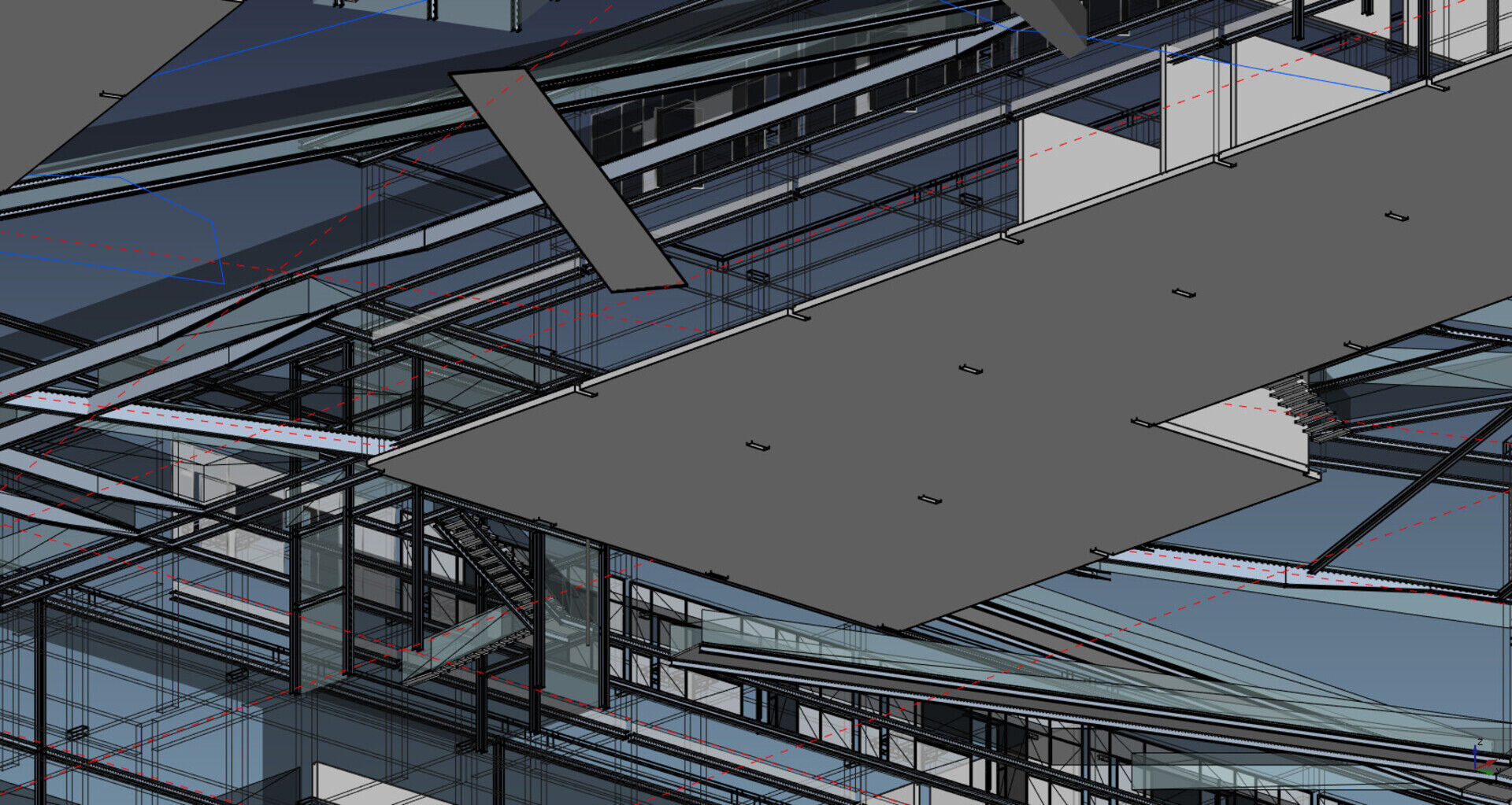
So here we are for our monthly report of what has been going on on the FreeCAD front this month. As usual, I will mostly talk about what I have been doing myself, but don't forget that many people are working on FreeCAD, so there is always much more happening than what I talk about in these notes.
To resume quickly, Werner has been busy working on the whole FreeCAD, as usual, but specially enhancing several issues in the tree view, making selection of large objects much faster, added several FEM tools, and fixed hundreds of other things. Looo has started merging core stuff from his Python3 branch into master (step by step, we will get there), WandererFan made a big update to TechDraw, Abdullah worked on better exceptions handling, and Realthunder is pursuing his work on PathArea, a set of tools inside the Path workbench, that work a bit differently than the others (they rely more on shapes).
But there is much more. For a deeper look at what has been worked on recently by me and others, check the commits log on github. Also, don't forget that more and more is happening outside the strict circle of FreeCAD source code, since it becomes more and more convenient to plug external workbenches into your existing FreeCAD installation. By the way, one of these external workbenches that becomes more and more interesting for BIM work, is Flamingo Tools. Check it if you haven't yet (look at the very professional pdf files in the "tutorials" folder)
So below are the highlights of what I have been doing recently. I also fixed a lot of small issues, but that are not worth mentioning here.
Don't forget you can help me spend more time on FreeCAD by collaborating to my Patreon campaign. This campaign is beginning to grow to impressive levels (special thanks to AlephObjects!) and I might soon have more impressive news to reveal! So next month I'll start improving it a bit, add goals and maybe rewards. I have a couple of ideas already. Don't worry, all of you early backers will automatically qualify for the whole suite 
Multimaterials

The most important feature I've been working on this month is a new Multi-Materials system. The idea is simple: Arch objects (and already some other FreeCAD objects, such as FEM) already have a Material property. If you give an Arch object a material, it will take the color of that material. Scripts and macros can already use the information contained in that material, for example the density, but so far that is all it does.
Arch objects can now, instead of a Material, take a Multimaterial. The multimaterial simply holds a list of materials, each with a given thickness:

This can already be used in Walls, Panels and Windows. Walls and Panels will use this to construct multi-layer walls and panels, and windows will use this to give a different material to each window part (frame, panels, etc). These objects all become multi-solid, and will contain a same number of solids and materials. With this, the paradigm change of the Arch workbench to multi-solid is now complete: Before, Arch objects were made of exactly one solid. Now, Arch objects can be made of one or more solids.
So far intersections of these multi-layer walls are not done automatically, I am still investigating the best way to achieve that...
Snapping and Working Plane improvements
With other users we were recently looking at Microstation's AccuDraw system. If you ever used Microstation, that is one of its most interesting features. Everytime you click a point to draw a shape (polyline, etc), you have an incredible amount of options available. The snapping system in Dratft/Arch is very much inspired from it, but there are still a couple of interesting features missing:
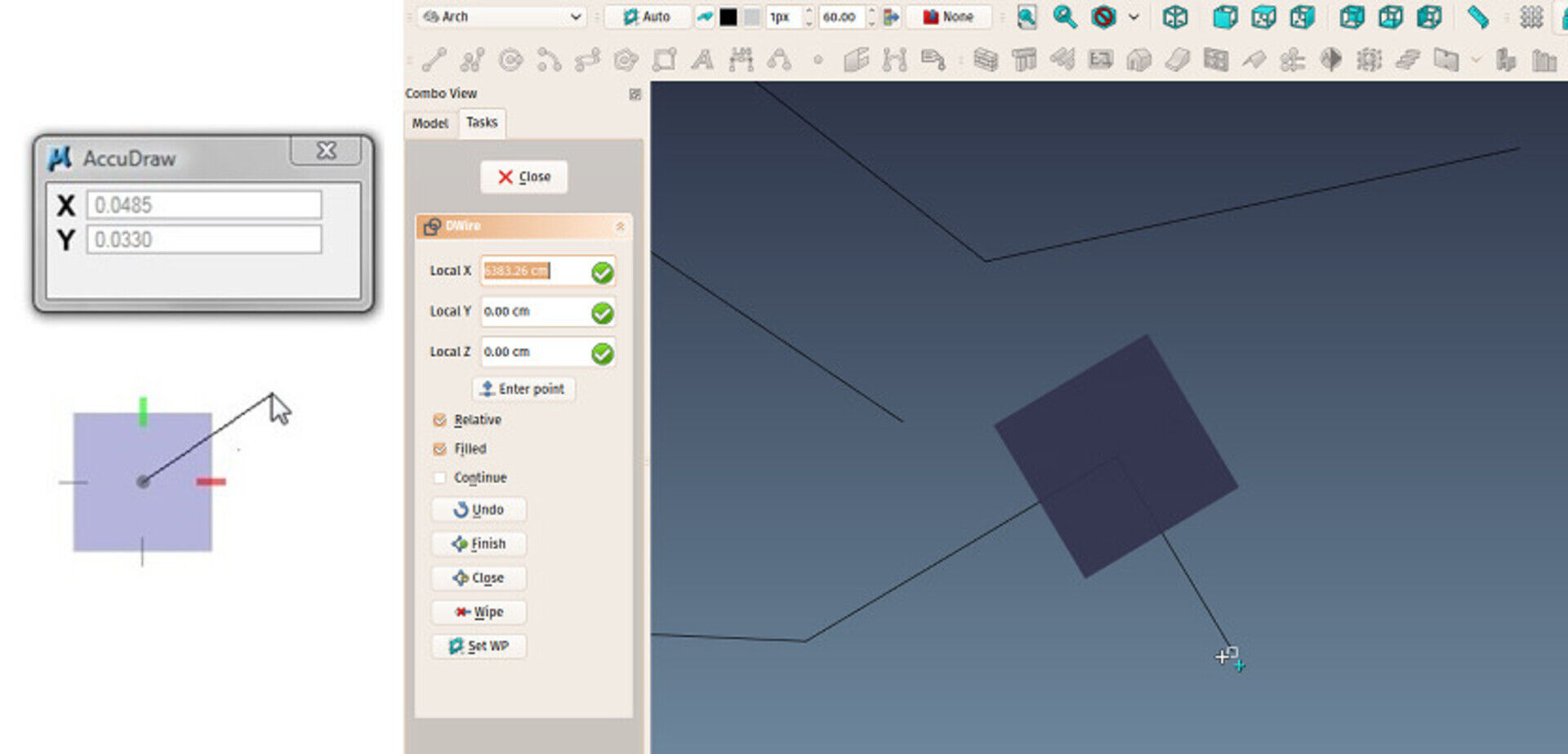
One first improvement is a new button in the task panel to realign the Draft working Plane while drawing a Wire/Polyline, along the latest segment drawn. This gives you a series of new alignment options and works very much like AccuDraw.
There are also a couple of new tools to place the Working Plane accurately: The Working Plane button now also works with 3 vertices selected, instead of a face, there is a new tool to place a Working Plane proxy in the document, that has the effect to save a working plane position. At any moment later, you can simply reset the working pane to that saved position.
Finally, I have added a couple of convenient macros to the Macros repository (remember that with FreeCAD v0.17 you can now install any of these macros directly from the Addons Manager): A first one rotates the view so it faces the current working plane perpendicularly, which basically allows Draft to behave like the Sketcher when drawing in a certain plane, and another that does the contrary: It moves the working plane so its center is exactly at the center of the current view. This is useful when you are drawing far from the working plane origin, and therefore you are out of the grid limits.
Wikilab
Another area I've been pretty busy this month, is not fully FreeCAD. It is our WikiLab project. By the way, I will have a chat online with people from the WikiHouse Foundation on youtube, on monday 29th. If this subject interests you, be sure to join us! I also recently wrote an article about the project for the WikiHouse website that you might like.
The project crowdfunding is also coming dangerously close to its end, if you have a couple of Reals to spare, please consider helping it, the experience gathered with it will be precious for everybody...
We also started cutting a couple of test pieces like these:
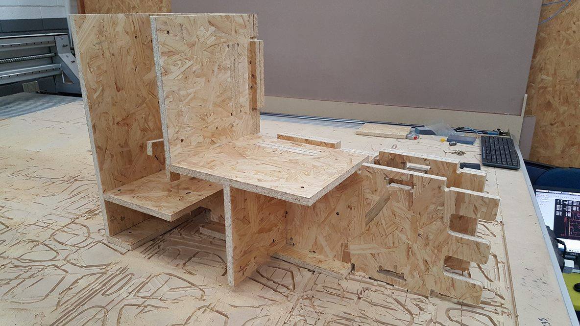
This was basically to calibrate the machine. One of the partners of the project is 123painéis, that is where the cutting (and part of the assembly too) is done. But it also served to test if OSB panels would work well, and I can tell you they work amazingly well. I was afraid the cut would be a bit rough, but the cut is just perfect, and the finish is very nice.
"Enough of that!" will you tell me. "What relation with FreeCAD does this have!" Well, a lot actually. To begin with, the project is entirely developed on FreeCD. Also, I did a lot of coding for the Path workbench which was a sponsored job, made with Brad Collette (sliptonic in the FreeCAD world) and Daniel Falck. But at that time, I didn't know much about CNC manufacturing. Many ideas were implemented under their guidance, but, I must admit it with great shame, without fully knowing what I was doing. Now that I'm going through the whole process, everything is making sense and clicking into place.
Also a lot of subjects, that I was aware already, such as tolerance, dogbones, nesting, etc. now required some thought from me. This didn't result into actual coding, but rather on design strategies. FreeCAD proves to be an amazing tool to work with these panel constructions, you can take high advantage of parametric objects. To give you a small example, all the holes are parametric. Changing a hole (adding dogbones) requires you to only change one hole to adapt the whole project.
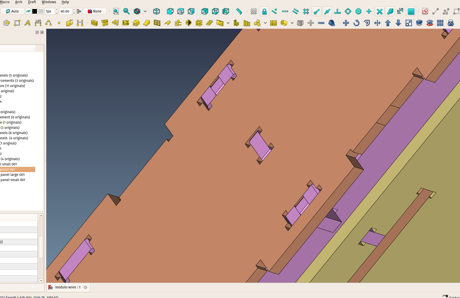
Be sure to check the main work file if you want to have a better look. All the project development is done in FreeCAD, the full model is also available here
All the generation of DXF cut profiles is automatic. The only missing part is automatic nesting, which is not easy. The only open-source app I found that can do nesting is SVGNest, unfortunately its code is very hard to adapt to FreeCAD. I'm currently studying it to try to understand how the algorithm works, and maybe try to rebuild it in FreeCAD.
Next step will be to generate the GCode directly from FreeCAD.
Start center redesign
I am also working on a new version of the Start Center:
It has several tabs, and will be vey configurable. You can play with it here, and discuss it on the forum if you have ideas.
Todo list
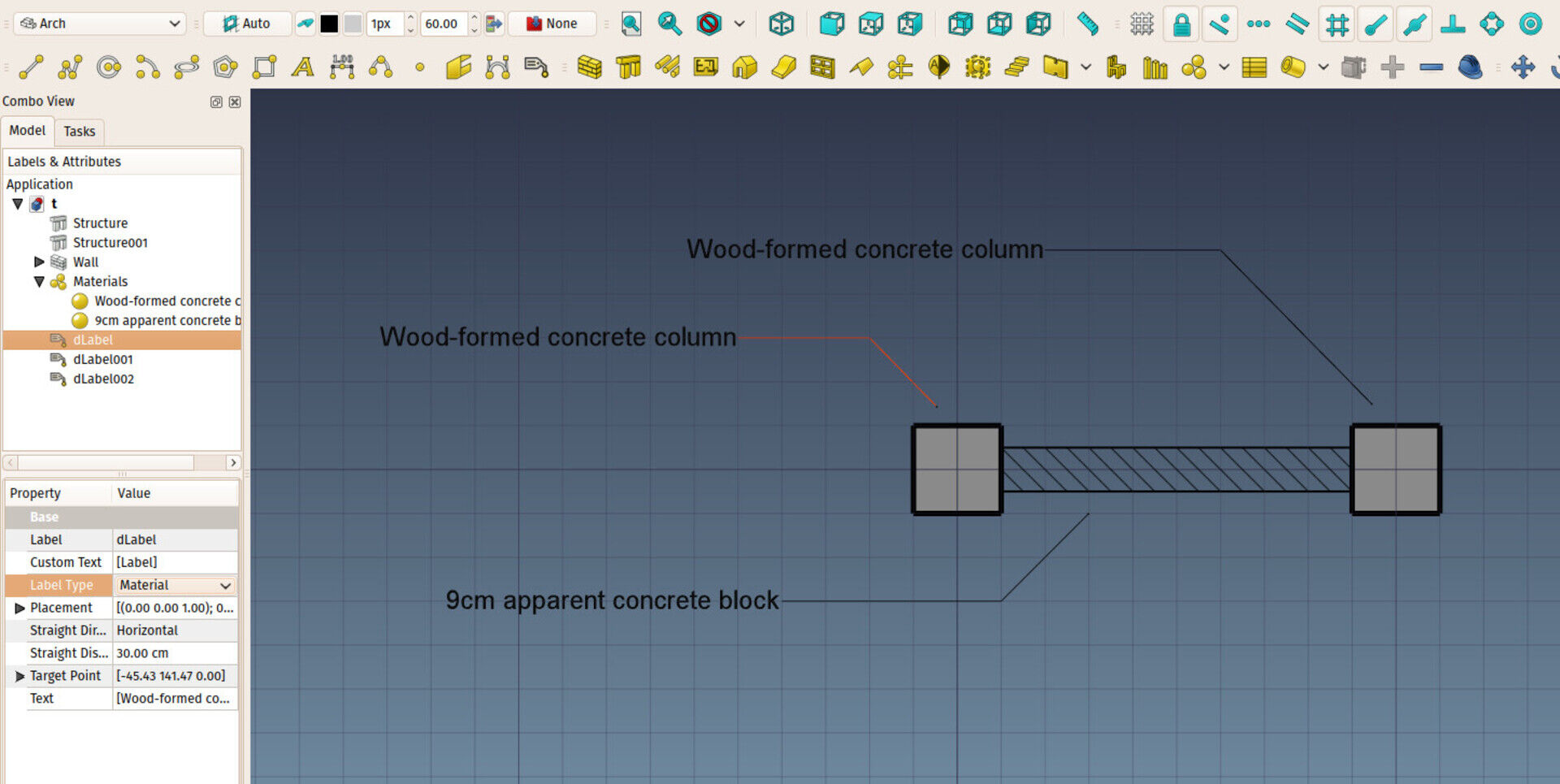
I will finish with adding here a couple of ideas I had while talking with other users, that I'm currently working on or will attack one way or another in the coming weeks:
- Add a "snap between 2 points" mode. That could be easily done with the new teporary snap points feature added last month:
- Add a "snap from" mode that allows you to snap to a certain distance from a point
- Add a system to check if addons need another addon or a specific python module
- Add a way to check if an update is available for a given addon
- Add a series of intelligent 2D BIM-oriented objects in Draft/Arch: Section marks (if possible placed automatically on TechDraw sheets), parking slots, vegetation symbols, etc...
- Add a kind of magic leader/tag object that can display automatically some info about its target object, such as material, name, size, etc... Similar to the series of tag objects in Revit.
- Adopt a wider concept for Arch Floors, that would embrace a much wider scope than simply floors, but could be used to gather other Arch objects in any kind of situation, not only per floor. It should also be based on App::Part to benefit from its nice handling capabilities (it can be moved like if it was one single object).


Can you ping someone to investigate? username: olddognewtricks email: nospam@ameritech.net.
Sorry again to pester you. Thanks!!


 But have a try at one of the 0.17 development versions, they are very stable already.
 I'm having the following difficulty in freecad.
My tools do not remain.
It's the macros!
Parts library
Work features
Pipe
How do I make them stay?
Can someone help me?
El problema concreto que tenemos es:
Tenemos un módulo implementado en C++ y utiliza directamente para modelar las funcionalidades que ofrece el OCE.
Creamos la estructura del módulo con la herramienta fcbt.py e incluimos todas los .h y .cpp en el CMakeList para que se compilen junto al FreeCAD.
Cuando compilamos lo hace bien, sin embargo cuando seleccionamos el módulo no da el siguiente error:
SpurGearGui.so: undefined symbol: _ZN11SpurGearGui13DlgCreateSpur16staticMetaObjectE
Le agradeceríamos mucho su ayuda en este tema pues ya hemos leído los posts y tutoriales de la página y no entendemos porque nos da ese error.
Por favor si pudiese responderme a **nospam**@uci.cu le estaría muy agradecido.
Gracias de antemano. Saludos.


Es difícil te ayudar así por aquí, es mejor te criar una cuenta en el foro de freecad en http://forum.freecadweb.org y postar (hay una sección en español) ahí hay más personas para ayudar... Pero debes describir los problemas que encuentras con más detalles y precisión, se posible con capturas de pantalla... El primero post de la sección explica como hacer.
En primer lugar deseo agradecerte el gran trabajo que haces compartiendo tus conocimientos y contribuyendo al desarroyo de FreeCAD.
Soy un usuario del sofware libre, tengo Fedora-25. Soy aficionado al diseño arquitectonico, vengo de usar AutoCAD y Revit.
He estado siguiendo los tutoriales de Obijuan orientados al manejo de FreeCAD en el diseño de piezas. He encontrado tu blog y es muy interesante y completo para adquirir los conocimientos que deseo sobre el manejo de FreeCAD orientado al diseño Arquitectonico. Pero tengo muchos problemas.
FreeCAD en Fedora no funciona correctamente, no funcionan bien los modos de navegacion, los componentes como ventanas,puertas etc...no toman bien las posiciones ni las transparencias en los vidrios. Las dimensiones en los muros son enormes, apesar de que los tengo configurados en el panel correctamente. no se que puede estar pasando. Te agradeceria si me puedes orientar a corregir estos problemas pues estoy muy interesado en poder diseñar con FreeCAD.
Otra cosa, perdona que escriba en español, pero no se Ingles. Entiendo el Portugues y el Italiano aunque no lo escribo correctamente. Muchas gracias, un cordial saludo.
FreeCAD Arch development news - april 2017
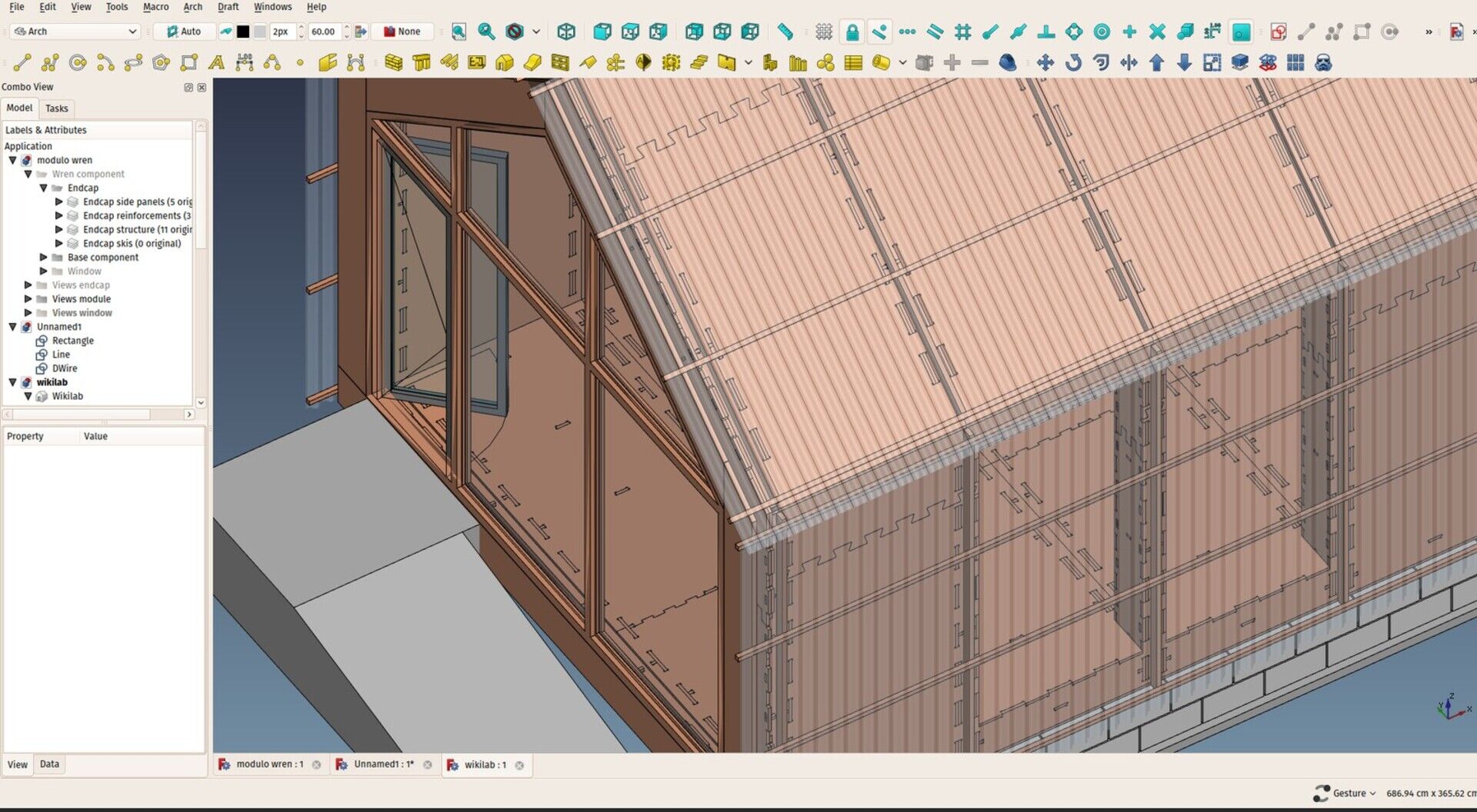
This is a short report of what I've been doing this month regarding the development of the Arch Workbench of FreeCAD.
At the beginning of this year I was complaining that the economical crisis in Brazil was making things hard here, and guess what, now we have so much work coming in that it got hard to find time for FreeCAD! This is something normal when you are working free-lance, it is always a roller coaster, but now thanks to my Patreon campaign there is a growing piece of stability in the balance, I need to find better ways to equalize everything. But it is really thrilling.
Also since a couple of months I got a major contribution from AlephObjects, the makers of the famous Lulzbot 3D printers. They are sponsoring not only me but a wide selection of people and open-source projects related to 3D and 3D printing (they are a major contributor to Blender). These guys are carrying on their shoulders a pretty big part of the open-source 3D world!
It would really be great to see more companies involved in supporting open-source projects development. For a company, supporting a project or a developer is a rather small investment, and is a much, much cheaper and interesting way to spend money than paying expensive monthly licenses to a software company just to be able to use their software.
By supporting the development of an open-source project, even with a small amount of money, a company would probably already have a big say in the development and be able to obtain features they need way faster than waiting for a software company to decide to implement them. Also, unlike when you are renting a software license, development and formation go hand in hand. Software companies might offer training programs, but it is always a short-term thing, while getting involved in an open-source project creates a much deeper, long-lasting and sustainable relationship between the company and the software, where training and learning and new features/versions is not just a service you buy once (and everybody who worked in a company knows that both these things wear off quite fast), but a permanent feature.
Okay that was my little minute of publicity, if you are a company, be as cool as AlephObjects, sponsor me! 
Now back to real news. This month I have been working mostly on small things, bug fixing, and small user experience improvements throughout FreeCAD.
New snap mode
Several applications (AutoCAD-based apps, Sketchup) have this "hold" system where you hover the mouse over a point for a certain time, then the software "remembers" that point and offers you new snap locations for it. Call me crazy, but I always got a bit annoyed with the fact that you have to wait a second or so with your mouse stopped, in the middle of a fast operation like drawing a polyline.
So I thought, why not let the user insert those hold points manually, wherever and whenever (s)he wants? It is now implemented, and it works pretty well: Press Q anytime, while drawing, to add such a hold point. New snap locations will become available orthogonally to that point, and at their crossings if you have more than one. This is really fast, and can easily be extended further.
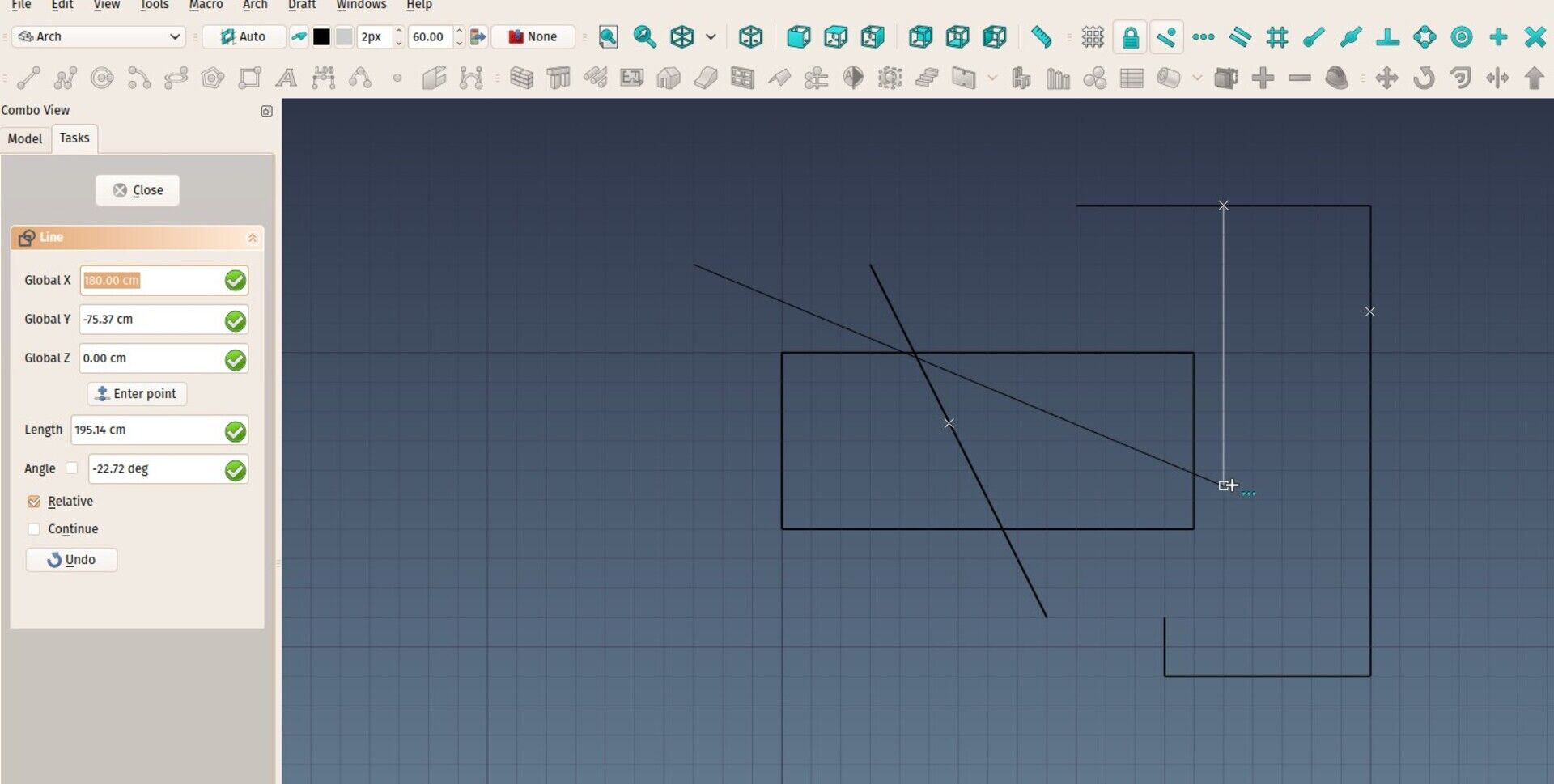
Support for materials and colors in DAE and OBJ import and export
This was a long-time issue, but it's finally done. When importing DAE and OBJ files (using the Arch OBJ importer), object color and transparency will be correctly rendered in FreeCAD.
When exporting to these formats, if the object has a material attached to it (currently only Arch and FEM objects can have a material), color and transparency will be taken form the material. If not, they will be taken from the object itself.
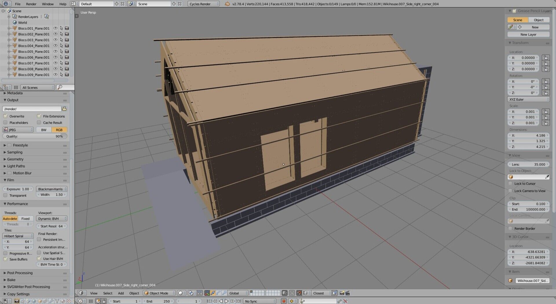
This makes exporting your architecture models to Blender for rendering much more comfortable, since all materials will be already there in Blender (same material/color in FreeCAD will create a same material entry in the OBJ or DAE file, and therefore in Blender).
Panels and Path
@sliptonic recently released an impressive video showing how the Path module could use the Arch Panels objects. We worked further on this, and added a series of improvements that pave the road to be able to comfortably build a model such as a wikihouse in FreeCAD, and be able to create, fine-tune and export g-code directly from it.
Misc FreeCAD-wide improvements
Small things have been fixed such as bugs in the DXF importer, small improvements to the object link dialog, the ability to define which wire of a window will cut the hole in its host wall, and bugs in the scaling of TechDraw views.
A couple of Arch utility tools, as well as the new Sketchfab exporter, have also been moved out of the FreeCAD source code, and are now in a new, separate WebTools. This will allow to bundle in that workbench a series of additional python modules related to web operations, that would be annoying to bundle in FreeCAD itself. This will make it much easier to install, and thanks to the new built-in Addons manager in FreeCAD, installing external workbenches has now become a piece of cake.
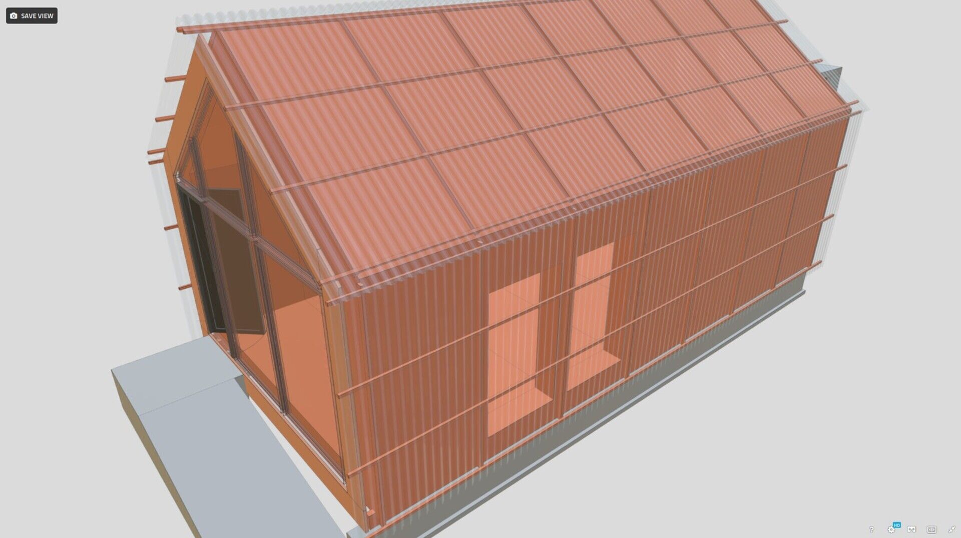
I also developed a new addon workbench to use CAD Exchanger to add support to several new file formats such as Rhino's .3DM or ACIS .SAT (which allows you to export Revit families to FreeCAD!). CAD Exchanger is a paid application, but I believe there could be a good synergy there, especially if they support more commercial file formats (also dreaming of decent 3D DWG support? Lobby them!), that are beyond the reach of an open-source project. And paying for a plugin to add commercial formats support to our favorite open-source app is something I would have no problem with, certainly I'm not the only one. Let's hope this synergy will flourish.
Major features
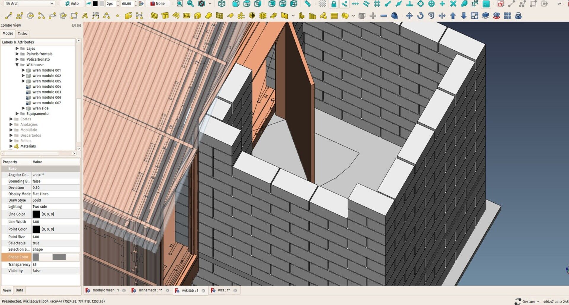
I have a large list of major features that I want to implement in FreeCAD and Arch, I've been talking about most of them in the previous development news, but these are all issues that require a lot of thinking, for example xrefs or walls. Very often I get comments like, why don't you make it work like in Revit (or ArchiCAD, or -name your favorite software here-). The thing is, you can rush and implement an interface quite quickly. But the really important part is not what the user sees or does, it's the underlying structure. If you design some user interface on top of a badly designed data structure, sooner or later you will get yourself limited by the limitations of your data structure. And it will be very hard to get around it if you designed a user interface already. But when you have a well designed structure, adding a good user interface on top of it is easy.
We had this discussion recently about the reinforcing bars tool in FreeCAD. It needs a better interface, that is obvious, but, more important, the reinforcing bar system behind it must be robust and flexible enough to be able to support any kind of crazy situations such as, for example, non-uniform (spline-based) curved walls. If we don't have that, sooner or later our model will fail to address a certain issue.
Then when we have such a powerful system, designing a user interface on top of it, which allows you to, for example, click a column and automatically place a series of reinforcing bars by just specifying a couple of parameters in a nice dialog box is much easier. And if you need a case that the dialog box cannot do, the underlying model can do it. You can still write a small python script that will solve the problem.
That development philosophy is at the deep roots of FreeCAD. Often newcomers complain about the lack of user-friendliness of the FreeCAD interface. But we use to think that there is a right order in software design: First make sure your base structures are powerful and flexible, then design the interface for it.
The interesting aspect is that I think we are entering a kind of new epoch in FreeCAD. Many parts of it are now pretty robust, flexible and stable. And there is a series of new developers coming in, interested in working on the interface side of things. This is also a very precise and long-term work, there is no magical solution, UI-wise. Everything is a question of testing, seeing what works best and what users like (an indication that it works well), and refining.
By the way, have you seen the revamped icons that @agryson has been working on? Also, don't forget that FreeCAD also support color and icon themes, thanks to the hard work of @wmayer and @pablogil...
Sorry for that long diversion, but there is quite some time I wanted to explain better that thing, "why FreeCAD still hasn't a better user interface". We'll get there, but first things first.
About the other major features I am still exploring and didn't find a good attack path yet:
-
Xrefs: I think we are close to something there (see the discussion ). I was first thinking to start with something hybrid with different "modes" where you can either make it insert, in the current document, a full copy of all the objects of the references document, with all its properties, or just a "condensed" view of those objects, but the digital project approach is totally doable and seems much more interesting.
-
Walls: Two things are becoming highly necessary: Support for more complex, multi-layer walls, and a more powerful system to join walls. Note that both these things are possible and working already, but the system is still a bit cumberstone. Multilayer walls is the easiest one to solve, what we need there is probably a kind of "super-wall" object, that would hold the different wall layers. The auto-joining is a more delicate issue. Currently, joining two walls makes them turn into one. But that's not cool, we need to be able to still manipulate these walls independently. Most apps do tricks to make them look like they are joined, but they are still independent objects. But I still didn't find a good idea to do that in FreeCAD.
-
Types: As I was writing in an earlier post, In Revit the concept of individual object almost doesn't exist. Everything is part of families (communism?). In FreeCAD, the individual object is king. Relationships exist between one and another, but the concept of a "family" is very shallow. However, working with families and types in Revit is really good. I'd like to introduce that more in the Arch workbench, and make objects more dependent on some more general definitions. However, how to do that without loosing the precious individuality, which gives a lot of freedom that Revit doesn't have? No clear idea yet.
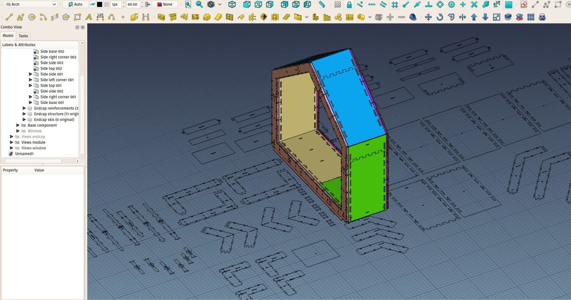
Sorry for that long read once again, hope you enjoyed, and I'll try to find ways to manage my time better next month! Don't forget you can help me to spend more time working on FreeCAD by sponsoring me on Patreon.
Also, have a look on our ongoing wikihouse-based project in Brasil, be sure to have a look at the FreeCAD files!
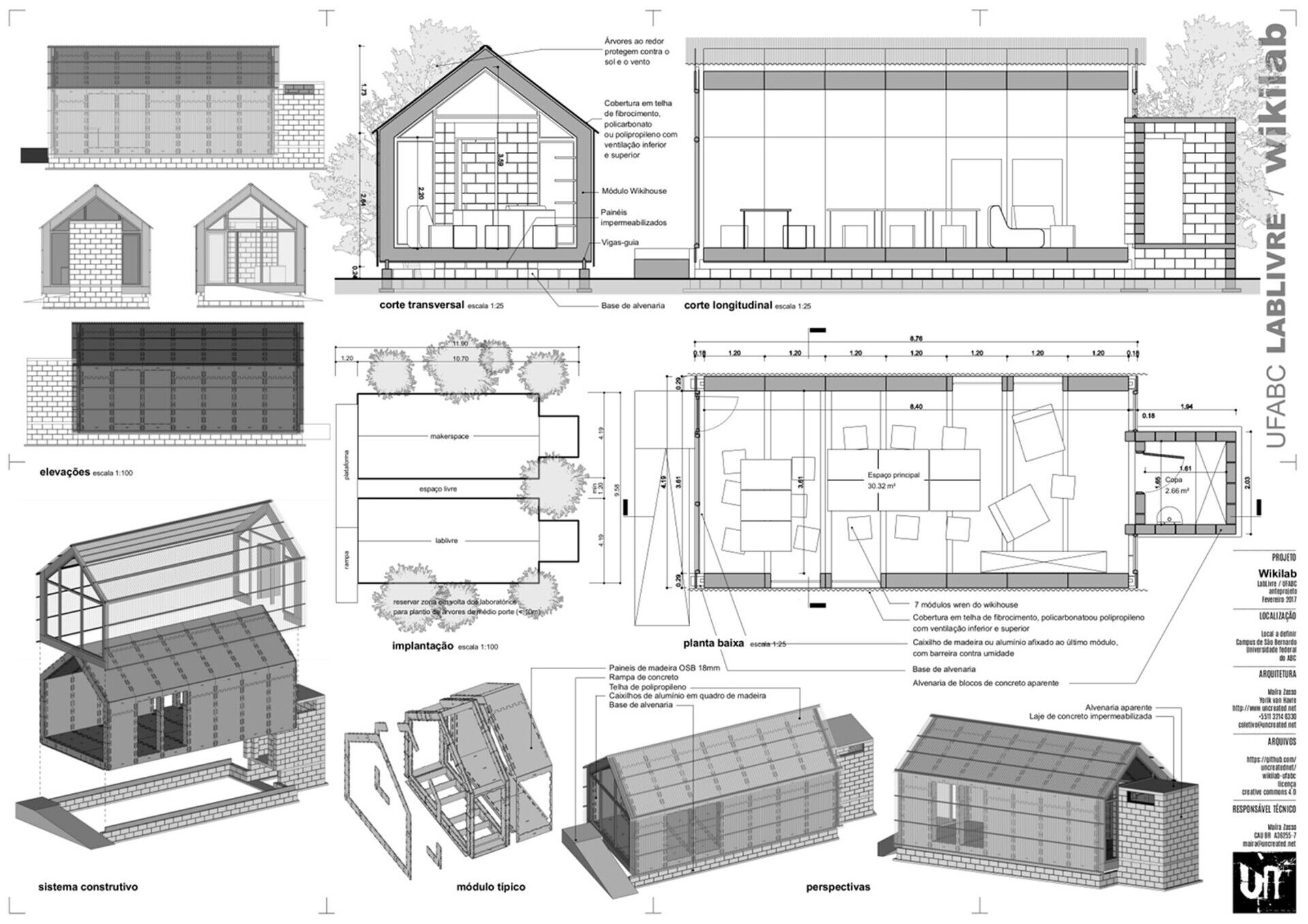
FYI, the image above has been heavily reworked in inkscape, but the sheet is originally exported from FreeCAD.
Best - Marco
These I made with Uban Sketchers São Paulo at the Água Branca park today:


There were made with Fabien in the city center this week:


And these a bit too fast last week at the MUBE:


As a complete novice to 3D parametric modelling, I had to make a decision in September last year whether it is worth my while to involve myself in it at all and, if so, would FreeCAD be the program worth my while investing in. After some research I decided, since I cannot afford the commercial packages anyway, to take the plunge and invest in learning the program and thereby grow together with FreeCAD. I downloaded the 12 very helpful 'FreeCAD Lessons for Beginners' and was soon able to tackle a complicated 3D architectural design problem that intrigued me for months that otherwise would have been too difficult for me to solve just making use of 2D methods. I also discovered that the parametric approach immediately enabled me to draw out site layouts program where missing dimensions sometimes have to be deduced from the others with far greater ease, which I then imported into my existing 2D CAD program - an immediate practical application for someone as 'green' as myself.
And now, 6 months down the line it looks like I may be doing my first full blown paid 3D job for a client on FreeCAD soon. This is blowing new life into a career that was threatened by redundancy. Very empowering.
I am delighted to read here how well FreeCAD is comparing with Revit. That is very reassuring.
Allow me to express my sincerest gratitude for the wonderful work you-, and the rest of the software development team, are doing.
If I may place my most pressing need on the 'development request wishlist' it would be for a series of tutorials for complete beginners, like those first 12 general ones I started off with, just focusing on the Architectural Workbench and BIM. I am really struggling to make proper full use of this workbench.
Regards,
Willem
Revit and FreeCAD

Last couple of weeks I've had the opportunity to do some work in Revit. This was highly welcome as my knowledge of that application was becoming rather obsolete. Having a fresh, new look on it brought me a lot of new ideas, reinforced some ideas I already had, and changed a couple of old perceptions too. So I cannot resist the temptation to do a little comparison between Revit and FreeCAD.
For who is not used to this blog, you must be warned that I am one of the developers of FreeCAD, and therefore my opinions here cannot be anything else than strongly biased. But for the sake of the exercise, I'll do my best to keep as neutral as possible, and look only at the technical side (I won't mention all the open source side of things).
The most important point I think, is that both pieces of software are surprisingly more similar than we use to think. Working in your spare time on a small open source project, and getting bashed all over the internet about how perfect Revit is, you end up thinking your humble work is phenomenally behind what thousands of Autodesk programmers can produce. It turns out that's a pretty wrong perception, I think. Both have their strengths and weaknesses, but FreeCAD comes out surprisingly well compared to Revit, and is actually better in many areas.
I'll start with what is similar in both apps. Both are fundamentally based on constrained sketches, that is, 2D shapes where you can put constraints (radius, length, etc), that you extrude to form 3D objects. Other extruded 2D shapes can then be used in boolean operations (union or subtractions) to produce the final object. So, very fundamentally, the modelling process in Revit is not very different than FreeCAD. In both apps, you'll find these profiles everywhere, underneath almost any object.
Both applications use reference planes to draw onto. In FreeCAD, there are several modalities depending on the workbench, but the concept is the same: You define a work plane, which is a plane in the 3D space, then you draw your 2D shapes on that plane, then you extrude.
The higher-level objects, like walls, structures, windows, etc... are in both applications convenience wrappers around these basic modelling tools. It would be a hassle to have to draw every outline of every wall you need in your project, so the wall tool does that for you, you just need to draw the baseline of the wall, and the whole modelling operation (make the 2D contour + extrusion) is performed automatically for you, and performed again every time you change something to the wall definition.
All the rest, that makes a full BIM application, is basically extensions around this modelling "core". It also surprised me how little the Revit core has been modified over the years. All the new features of these recent years are in that area around the core, not the core itself. This is not necessarily a bad thing, when you think of it, BIM work is composed of a very big part of theses things that are not solely 3D modelling.
The bad sides of both applications are also surprisingly similar, and, even more surprising to me, equal in number and annoyance. In FreeCAD, due to its young age, and the fact that there is too little work spent on the BIM module (don't forget you can help me to remedy the problem!), all kinds of shortcomings, limitations and incomplete features cross your path all the time. Fortunately you can work around these most of the time, and your ability to find and use these workarounds grows with your FreeCAD experience, up to a point that it doesn't annoy you anymore. That typically happens with all FreeCAD developers, so it's important that new users report the problems they encounter.
In Revit, my impression is that you basically encounter the same amount of annoyance. My even deeper impression (a secret I won't hesitate to reveal to you now, exclusively!) is that in the perfect world of Revit, where "everything works", so to speak, programmers are extremely reticent to add anything that could "stain" that perfect model. So all kind of external, hybrid, workaround features are vetoed or minimally implemented because they couldn't avoid, but highly discouraged.
But, more useful than the rant, I also made a list of points that I found good in both applications, with the obvious idea to gather things to improve in FreeCAD.

Revit strengths
- The workflow is totally adapted to architecture. This is really a joy to work with. All these little annoying tasks you have to fill your day with, put annotations, make a list of this or that, have some kind of automatic tool. Revit has few tools and buttons, but all of them are a typical architect's task. I don't think any other BIM app offers so much comfort to the architect. No wonder once you begin to use it, you are hooked.
- Autocad-like output: What comes out of the 2D views is really a perfect AutoCAD-like output. With lines, hatches, everything. And you can draw on top of it, which allows people new to Revit but used to AutoCAD to hack their way our of problems very easily, at the cost of infuriating Revit pros around, maybe, but at least you can get the job done even if you are new to it.
- Hundreds of auto 2D objects: I guess that's the most valuable thing Autodesk has added around the Revit core: All the whistles and bells that you used to do manually in AutoCAD, are now smartly handled by some automatic tool: Automatic leaders that pick a value of what they are showing. Automatic tables that gather all the notes found in a view. Automatic section marks that update with the page number the section is in, etc.
- Autocad hatching and "syntax" everywhere: The 2D output of Revit is ready to be worked on further and natively in AutoCAD. I don't think any other BIM app produces so nicely editable DWG files.
- Ease to work in 2D views: Revit is made mostly to work in 2D views. Many tools are in fact only available in 2D views. But one has to admit they are very comfortable to work with. The hidden lines system is mostly cumberstone in the 3D view, but it takes all its meaning in 2D. You really work on a 3D model like if it was a 2D drawing.
- Ease to manage objects by category: The categories of Revit objects (families and types) are very strict. Objects that don't fit in these categories (for example imported objects) are almost useless in Revit. However, this has its advantages too, all the "siblings" relationships that exist, for example, between several types of the same family, or under a same category, are pretty powerful. In Revit, designing object categories is almost more important than desinging individual objects themselves.
- Fast 2D views: Revit pseudo-experts out there will quickly tell you that it's because Revit is a database, doesn't generate its 2D views, and (insert commercial bla-bla shit here), but the fact stays, screen views must be generated, and hidden geometry must be calculated. When an object changes, all the views where it appears must be updated. And this is really fast in Revit.

FreeCAD strengths
- The workflow is not specifically adapted to architecture: This is the exact opposite of Revit's first strength. FreeCAD is a generic application, and not a specialized one. This will give you less comfort, but bring a wide series of tools, workflows, solutions or ideas coming from other areas (mechanical engineering, etc). There is always a wide series of possible ways to achieve something, so you (almost) never find yourself in a "this cannot be done" situation. Also, being not specific to architecture, FreeCAD can easily be used by people who are not architects, to design buildings or parts of buildings, their own house for example.
- Modelling is very powerful and free: Modelling capabilities in Revit are limited. In no time you find yourself in front of something very hard or impossible to model. In FreeCAD it's really hard to find something you can't model, and if so, it's easy to use geometry modelled in other applications.
- A complete tree: Revit doesn't show you each and every object in its tree view / project browser. FreeCAD does. That has a lot of advantages.
- FreeCAD can work much more easily with dumb or bad geometry: In Revit, for an object to be workable with, it must comply with many rules dictated by the general structure of the modelling core. Basically, it must be an extrusion, its base 2D shape must be translatable to Revit's 2D system. Otherwise you can do very little. FreeCAD on the other hand can even work with mesh data and use that in BIM workflow. An important consequence is that importing stuff from IFC integrates much more seamlessly in FreeCAD, while in Revit it's a very delicate matter.
- Freedom to organize model as one wishes: In FreeCAD you have many ways to group objects together, and group these groups inside other structures. So you have a very big freedom to organize your model as you like. If you don't want to use the levels/floors system, no problem. If you have something that's not exactly a building, together with your building, it's easy to create a specific structure for it. It makes you also think about how to organize yourself, which is good.
- Ease to work in 3D view: As much as the 2D views of Revit are comfortable to work with, the 3D view is not. The 3D view of FreeCAD is really a joy to work with, comparatively. You can easily hide/unhide or temporarily change the display style of individual objects, select part of objects, and visualize well all the reference and work planes. Here, you can really work in the 3D view.
- Ease to work with other kind of data from other people: Revit can, with many limitations, work with IFC and DWG files, and you'd better keep them as linked (unmodificable) files, not try to import their geometry to do something meaningful with it. In FreeCAD, on the other hand, it is pretty easy to turn anything into a valid FreeCAD (and therefore BIM) object: IFC or DWG objects, but even mesh objects from Sketchup or Blender.
- Happy mix of imperial and metric units: There is no such thing as a template in FreeCAD. You could work on a model in centimeters, hand it over to someone in the US who will see everything expressed in inches. Internally, FreeCAD draws everything in millimeters, always. Only what you see on screen is expressed in the unit of your choice. You can also always insert values in any unit, no matter what the current scheme is, or even mix units in a same expression.
- Easy to manage objects one by one: Contrarily to Revit, where the power lies in categories of objects, the focus in FreeCAD is on the individual object. It is easy to turn individual things off (and turn them back on afterwards), modify a single instance of something without the need to refer to categories or families. You can easily recreate a similar workflow as families, by basing several objects on the same one (clones), but this doesn't tie the clones to their "master". You can give them another master anytime, or grow something else on top of them, using the "family" only as a base. You can do all that in Revit as well, of course, but I find it already much more flexible in FreeCAD.
- 2D modeling tools are more powerful: Hard to believe, but it's true. Have a look at what is possible with the Sketcher, there is already much more than what Revit offers.
- Proper MDI: Working with multiple documents in Revit is still pretty cumberstone, to say the least. Why the hell must a reference be unlinked when you open another document containing it too? FreeCAD has a standard, normal way to work with multiple documents, they can all be openend in parallel, you can display them all together, etc.
So no more shame, let's claim it loud, yes, FreeCAD is as good as Revit! "As good as" doesn't means "the same", though, and their philosophy and workflows are very different. Revit will give you more comfort and speed, FreeCAD will give you more freedom. I don't know if we'll ever reach the comfort level of Revit (I'm not convinced that it wouldn't force us into options that would harm the freedom side), but on the question of speed, there is still a lot to be done, no doubt we'll still see huge improvements in that regard.
I took note of a series of small things I'll try to fix or add in FreeCAD, but also identified these more generic areas that I'll try to improve in FreeCAD:
- References: At the moment there is no reference system in FreeCAD that allows you to split your work in several files. This is a huge question, that has complex implications in FreeCAD's internals, and that the PartDesign people is already on their way to solve. However, we might start experimenting with something directly usable in BIM workflows.
- TAB key cycles through snaps: I find that pretty good in Revit. Currently, in FreeCAD, only the "closest" snap location is kept. We need instead to keep all of the snap locations in a certain radius, order them somehow, and allow to hit a key to take the next one on the list.
- Remember last "hold" snap point: When hovering the mouse without moving for a certain time, that point should be remembered. Then, additional snap locations should become available on horizontal and vertical lines passing through that hold point. This needs a little more thinking to define more exactly what these additional snap location should be.
- Wall layers: In FreeCAD, wall layers can already be made by basing several walls on a same baseline. but this should be developed further so the handling of these walls becomes more user-friendly. Perhaps a new multi-layer wall object, that would include and manage the individual parts. This needs more thinking as well.
- Walls joining: Currently there is no automatic wall joining in FreeCAD. You have to join walls manually, by adding one as a sub wall of another. I'm not sure I like Revit's way too much, because you cannot see clearly where one wall ends and the other begins. You cannot see in Revit what will be exported to IFC, for example. But nevertheless, when you have multilayer walls, it becomes very convenient to have proper wall joining based on materials. Here again, we need a better plan to know how to achieve the goal.
- Hi-res system: The Arch Equipment currently has a system to display a high-resolution mesh instead of its shape. This high-resolution mesh can then be used when exporting to mesh formats such as OBJ. This system should be extended so it supports a higher-resolution shape as well, and applied to all Arch objects (ex: brick wall, or wikihouse panel compounds). There is a basic version working already.
- Better support of IFC properties: Currently all IFC properties found for an IFC object are stored in a simple dictionary (property sets are discarded), and the contents of that dictionary gets saved to IFC properties when exporting to IFC. We need something more complex, that keeps track of which property belongs to which set, and the ability to modify and save that structure back faithfully when exporting to IFC. I'm already working on this too.
- New DXF export: The current DXF exporter is still based on the old python library, we need to recode a new, faster one in C++ like we did for the importer.
With OpeningDesign we are also trying to build a "best practices" manual to transfer data between FreeCAD and Revit (and hopefully other software in the future).
PS - Half the stuff on the images in this post was done by Ryan
FreeCAD Arch development news - March 2017

I'll start adding a date to these "Arch development news", it will be easy to look back and motivate me to write them more regularly. A monthly report seems good I think, no?
Hi all,
Long time I didn't write, but that doesn't mean things have been quiet
down here, it's actually more the contrary. To begin with, I've had the
opportunity to do a job with Revit. There was a long time that I didn't
really use Revit intensively, so this was a great opportunity to get back
on track with it. I gathered a lot of observations, ideas, and things that
compare quite favourably to FreeCAD (favourably for FreeCAD of course  ).
This is too long to put here, but I have written another post specifically
about that, that I'll publish later this week.
I also collected a long list of Revit rants, but since a lot of people are doing that all over the net already, my article will rather concentrate on the positive points I found in both apps.
Now the ideal would be to get an ArchiCAD job! Anyone has an ArchiCAD job for me?
I've otherwise been working on a couple of own projects directly in FreeCAD, and implemented a couple of new features o the way:
Add-ons manager

This is not only mine but a real teamwork. Finally we have a simple but functional tool inside FreeCAD to install external workbenches and macros. No more need to go to the web, download and install, all this is done directly from within FreeCAD. Installing workbenches will still require you to restart FreeCAD, and it's currently still not very enjoyable to browse and explore available addons, but we're working on it.
Hi-res mode
In Revit, objects can display 3 levels of complexity: coarse, medium and fine. For each of these levels, you can define geometry that must appear or not. So for example, you can have a sink object that is made of a box and a more detailed curved geometry. Then you set the box to only appear in coarse mode, and the other geometry to appear in medium and fine.

In FreeCAD I now implemented a similar concept. It is still in test, so it might change depending on what people think of it and how it resists day-to-day use. Basically, each Arch object now has a new "Hi Res" property which is a link that can point to another object. They now also have a "Hi Res" display mode. If you set the display mode of the object to "Hi Res", and the object has its Hi Res property set, the geometry of the HiRes object is displayed, instead of its own. This happens entirely at the 3D view level, so the Arch object keeps its own shape. It only displays another. But selection still works, inside the 3D view you don't see that it's not the real shape of the Arch object.
Of course so far other tools and workbenches (TechDraw, etc) are unaware of this, and will continue to look for the objects shape. But if the system works well, it will be easy to simply use the Hi Res shape instead, if present.
So this is not Revit's (or ArchiCAD's) coarse/medium/fine system, but it seems to me that the cases where you really need three different levels are rare... And if three, why not four then. This systems seems much more flexible to me, you can basically use any shape/object (meshes too) as hi-res version of another, with all the possibilities and flexibility that this offers. And, if we need a third mode in the future, most of the work will be done already, it won't be much work to add it.
In the image above, the concrete blocks are the Hi-res version of the walls, and the wooden panels, with all their cuts, too. Check the whole file too (you will need a very recent version of FreeCAD).
There is a discussion thread about this feature on the forum, all ideas are welcome!
External references
This system has another aim too: It paves the road for a pretty powerful external reference system we're currently thinking about (discussion thread here: Everybody used to Autodesk applications knows the X-Ref system: You have a file, and you embed it into another file. However, if you know this, you probably also know the bad side: If you embed a couple of heavy files, your "master" files becomes quickly unbearably slow. People coming from the mech engineering world, and software like Solidworks or Catia know another way: You cannot simply embed any file into any other. You need to prepare the base file somehow, either by organizing your objects inside somehow or by saving it under another file type, the methods differ.
But this could give way to an amazing idea, that Jürgen (FreeCAD's idealist and godfather) emitted several years ago already, and that is not even ours, since it has for example been implemented in Digital Project. Anyway, in the software world, as in all the culture world, nothing is really only your idea. It's always something that travels... Okay okay, the amazing idea: When embedding a file, instead of bringing the whole contents into the host file, you would only bring a lightweight version, or a "ghost" of it. In FreeCAD terms, that would mean only importing the OpenInventor representation of the objects contained in the file, which is what the 3D view of FreeCAD is made of. In other terms, you would bring only the 3D representation, not the BRep geometry.
Without the BRep geometry, you can go very far. The 3D view of FreeCAD can display several millions of polygons without problems on an average system, and keep everything pretty fluid. In the case of BIM, this could probably allow to display huge and complex buildings with all their details. All the heavy calculations would be left in the embedded file, and not be used in the host file.
But the OpenInventor representation is currently not stored in FreeCAD files (it is calculated by the engine on-the-fly). We need to find a way to store it, so another file could just load that representation, and nothing else, without the need to calculate it.
The easiest way seems to be the PartDesign way: You place all your geometry inside a "body" object, which stores a copy of the OpenInventor representation of its contents. When you load the file from somewhere else, you could just load that representation, and you would get a lightweight copy of the body contents.
Of course. that's the plan with PartDesign. But on the Arch side, we have an opportunity to do some testing quicker than there, firstly because Arch is programmed in Python, which makes it much easier to experiment, and secondly because less people are using it, so we need to be less careful, it's not such a big problem if we suddenly break something. And it happens a lot in FreeCAD, that some features are tested and tuned in Python first, and then some day become fast, rock-solid C++ features.
So that's the plan, and the Hi-Res system was a first step in playing with these concepts, now the way is open to try to play with external files too.

SketchFab exporter
Do you know SketchFab? It is a platform where you can upload 3D models and view them inside a web browser, without flash or any other plugin (it uses webGL which is now built in all major browsers). SketchFab has free and paid accounts, and although the platform is not open-source, the team behind it is very friendly to open-source projects (some people behind it actually come from the Blender community). I begin to use SketchFab more and more, because it is very easy to show models and ideas to clients with it, without having to make them install software.
So this week I [coded an exporter] for it, which now lives in the Web workbench of FreeCAD. All it requires is to create an account on SketchFab, select the objects to upload, give a name and a description, and press a button. SketchFab has a pretty good built-in scene and material editor that allows you to fine-tune your model afterwards.

The exporter offers your several formats to export to, the one that works best for BIM models is the OBJ + MTL, because it will carry better materials info, but there is one mode that is particularly interesting which is the .iv (OpenInventor) mode, that literally sends to SketchFab a copy of the 3D view of FreeCAD, which gives very nice results:
So this could become a very good way to showcase your FreeCAD models to people who don't have FreeCAD.
Working Plane and View Style fixes
Recently I had to work with models with a lot of non-orthogonal planes to work in. It is always when you have to eat your own dogfood that you become painfully aware of the shortcomings. Switching workplanes is very quick already, select a face, press "WP" and it's done, but there were two problems: first there is no way to set your view perpendicularly to the current working plane, which is often useful, and, if you choose one of the ortho planes (XY, XZ or YZ) very far from the model origin point, you won't see the grid.
So one thing I added is a checkbox in the "Select Plane" dialog to recenter the grid to the center of the current view. And another little utility is a macro to Align the view to the currnt working plane. If you install that macro (which is now easy with the addons manager!) and give it a keyboard shortcut, the workflow becomes very good: Select a face, press WP, then press the key you used as a shortcut for the macro, and you find yourself looking perpendicularly to your working plane. If you have the Snap to Working plane button on, then you are really working in a perfect 2D environment, like in the Sketcher.
The different Draw Styles of the FreeCAD 3D view have also received keyboard shortcuts, and Werner added two more modes. One of them, named "shadeless", gives actually very nice "hidden lines" aspect, you would almost think you're in Revit!

Don't forget you can help me spending more time working on FreeCAD, by sponsoring me on Patreon. Every dollar is a little more time I can dedicate to it!
As the tradition dictates, I put a couple of images of what I'm working on at the moment:


Thanks again!
Pierre
FreeCAD Arch development news
A long time I didn't post here. Writing regularly on a blog proves more difficult than I thought. I have this blog since a long time, but never really tried tomconstrain myself to write regularly. You look elsewhere a little bit, and when you get back to it, two months have gone by...
Since this post is aimed principally at informing my Patreons of what I am doing with their money, I'll start by saying thank you again, the last year has been a terrible economical crisis here in Brazil, and the last months have been awful, we thought seriously we'd need to close our architecture office. Fortunately things seem to slowly get back on track... Anyway, thanks to your support, even in the direst hours, I could still reserve a little time for FreeCAD, that is really very cool.
So the main happening, on my side, was without a doubt the new Panel tools I've been working on, that now allow to create Wikihouse-like projects fully in FreeCAD.

Arch Panel objects have been enhanced so they can now 1) have a tag, 2) output a 2D view of themselves, in the XY (ground) plane, including the tag, and 3) a panel sheet object can gather and assemble different of those outputs, and 4) you can export these panel sheets to DXF, with a result that is identical to the ones produced by the Wikihouse project.


By the way, the above image is a screenshot from LibreCAD, which started as a fork of QCAD, but now the two projects have evolved in very different ways, QCAD has become quite powerful, while LibreCAD stayed more simple. However, LibreCAD has recently added DWG support, which was entirely coded from scratch by Rallaz, one of their code warriors. This is truly impressive, given that the DWG format is proprietary, undocumented, kept as secret as possible by Autodesk, and even more, it changes radically each year. At FreeCAD we gave up a long time ago... Kudos LibreCAD heroes!
Getting back to wikihouse, once you have a set of profiles for your panels, it is now pretty easy to build complex wikihouse models, then quickly output the cut sheets for everything, no matter how they are assembled in the model.
There is much room for improvement of course, and we didn't even touch the possibilities offered by the Path workbench yet. However, I thought this is a safe and comfortable in-between step, the DXF output allows to check the results before preparing the actual cut, and it mimics the current Wikihouse workflow.
Another small feature, that was in the works since long, is an AutoGroup feature (it only works in Draft and Arch at the moment). With it, you can basically get the kind of workflow you have in your favorite BIM app: Switch to third floor, and begin to work on third floor. In FreeCAD, you would hide all floors except the third, then enable autogroup on the third floor, and there you are.
On other fronts, there is much going on, as always, in FreeCAD. Werner has made a ton of fixes and reinforcements here and there, as usual (for who doesn't know, he is the unsung true hero of FreeCAD, everybody is an amateur compared to him), Ickby is working on several ground improvements to the general document structure, and, last but not least, Abdullah has coded the one feature we were all waiting for but were too afraid to code, B-Spline support in the sketcher.
I also fixed a series of smaller bugs (these little things we never talk about, but that, when accumulated, really build the stability of an application), while working with Ryan on one of our Revit/FreeCAD experiments. I'll finish with a couple of screenshots of the FreeCAD work I've been doing there. All of this now exports perfectly to IFC, and imports (more or less) perfectly in Revit.


Beste wensen ook!
Groeten
Bedankt om tutorials en overzichten voor FreeCAD online te zetten. Ik installeerde FreeCAD 2 dagen geleden en ben vast besloten om mijn huis er mee te tekenen (startend van de papieren plannen). Ik kan dan makkelijk verder voor het plannen van het inrichten van de zolder.
Gezien je een berichtje in het Nederlands wou, bij deze. Mijn beste wensen voor 2017.
mvg,
Peter


